MRI gradient waveform design using convex optimization

a gradient waveform and optimization technology, applied in the field of magnetic resonance imaging, can solve the problems of many of these methods limited to the design of trapezoidal pulses, and achieve the effect of reducing the time in identifying

Active Publication Date: 2007-11-27
THE BOARD OF TRUSTEES OF THE LELAND STANFORD JUNIOR UNIV
View PDF13 Cites 31 Cited by
  • Summary
  • Abstract
  • Description
  • Claims
  • Application Information

AI Technical Summary

Problems solved by technology

In particular, the design problem is to minimize gradient waveform durations subject to both hardware constraints and sequence constraints such as desired gradient area.
Many of these methods are limited to the design of trapezoidal pulses, and most have been demonstrated for 1D gradient design.

Method used


Image

  • MRI gradient waveform design using convex optimization
  • MRI gradient waveform design using convex optimization
  • MRI gradient waveform design using convex optimization

Examples


Embodiment Construction

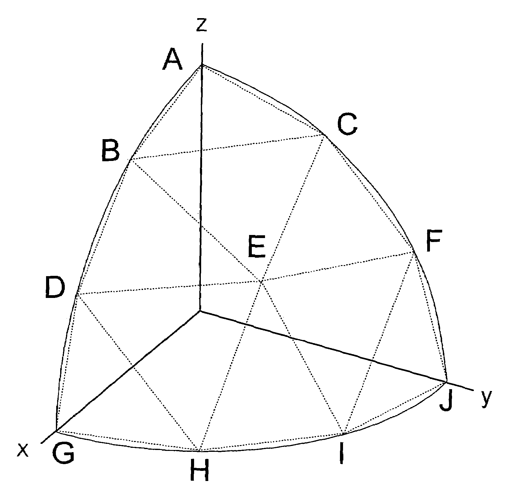
[0025]The design method can be used in accordance with the invention to design minimum-time gradient waveforms that satisfy gradient-amplitude and slew-rate limitations. Additional constraints such as gradient start and end amplitudes, gradient area or higher-order gradient moments can be included. Importantly, application of the method can be extended to multi-dimensional gradient design which is necessary for procedures that use oblique scan-plane orientations.

[0026]Consider first the general constraints in gradient waveform design including gradient amplifier voltage and current limits as well as pulse-sequence requirements. Next, methods of formulating the problem are described so that it can be solved using three different types of existing linear and quadratic programming techniques. All of these techniques result in comparable solutions.

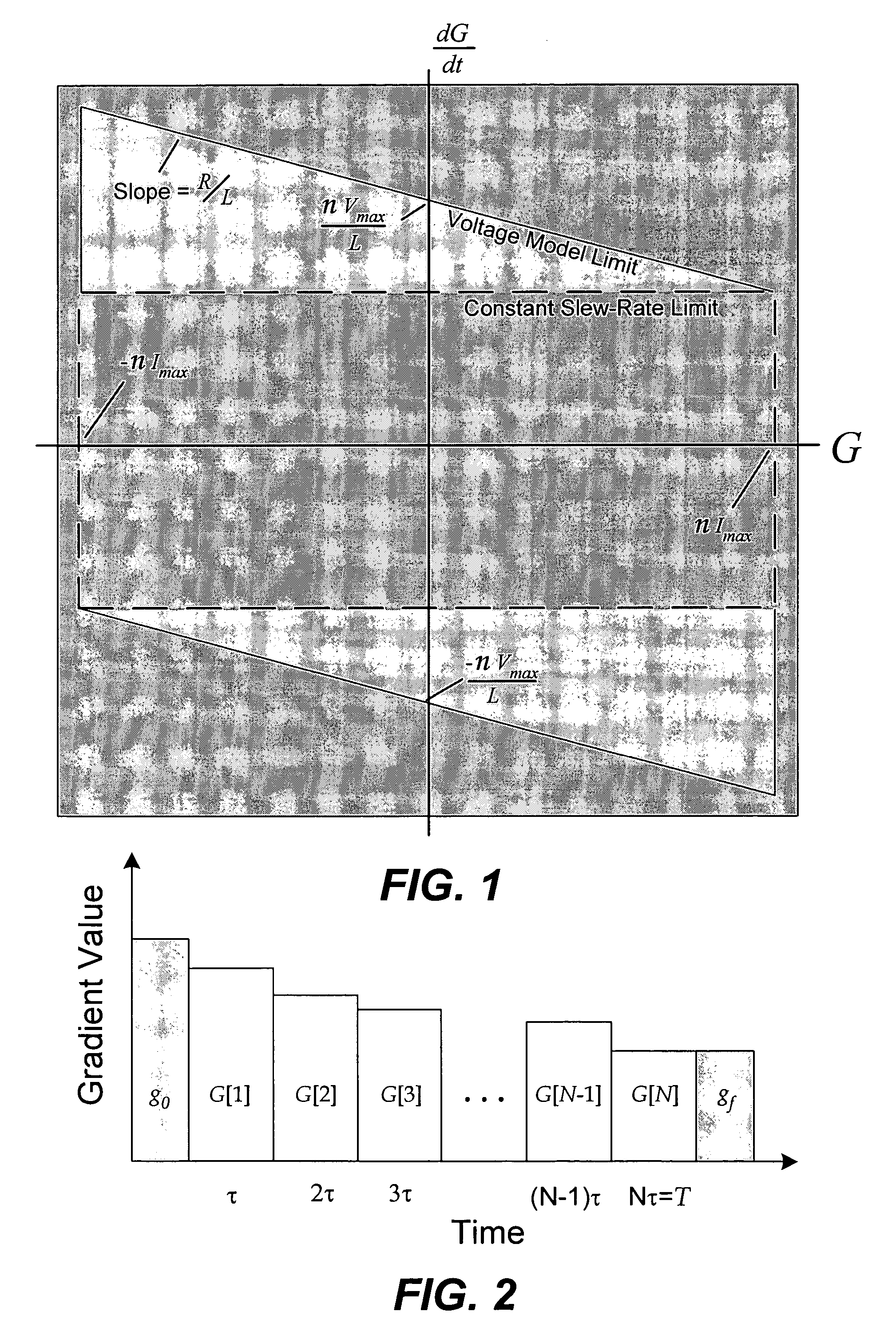
[0027]A gradient amplifier supplies current to a gradient coil, producing a continuously-varying gradient, G(t). The amplifier has current an...


PUM


Abstract

A time-optimal MRI gradient design method utilizes constrained optimization to design minimum-time gradient waveforms that satisfy gradient amplitude and slew-rate limitations. Constraints are expressed as linear equations which are solved using linear programming, L1-norm formulation, or second-order cone programming (SOCP).

Description

STATEMENT AS TO RIGHTS TO INVENTIONS MADE UNDER FEDERALLY SPONSORED RESEARCH OR DEVELOPMENT[0001]The U.S. Government has rights in the disclosed invention pursuant to NIH Grant Nos. NIH-HL39297, NIH-HL56394, NIH-AR46904 and NIH-CA50948 to Stanford University.BACKGROUND OF THE INVENTION[0002]This invention relates generally to magnetic resonance imaging (MRI), and more particularly, the invention relates to the design of magnetic gradients for use in MRI.[0003]Magnetic resonance imaging (MRI) requires placing an object to be imaged in a static magnetic field, exciting nuclear spins in the object within the magnetic field, and then detecting signals emitted by the excited spins as they precess within the magnetic field. Through use of magnetic gradient and phase encoding of the excited magnetization, detected signals can be spatially localized in three dimensions.[0004]Advances in MR system hardware enable the use of new rapid pulse sequences. Typical rapid sequences include rapid gra...

Claims


Application Information

Patent Timeline
Patent Type & Authority Patents(United States)
IPC IPC(8): G01V3/00G01R33/561
CPCG01R33/561G01R33/4824
Inventor HARGREAVES, BRIAN A.CONOLLY, STEVEN M.
Owner THE BOARD OF TRUSTEES OF THE LELAND STANFORD JUNIOR UNIV
Why Eureka
Try Eureka