Vehicle safety warning device

a technology for warning devices and vehicles, applied in vehicle position/course/altitude control, process and machine control, instruments, etc., can solve problems such as failure to provide apparatus, methods, devices, and devices that detect hazardous road conditions based on road surface temperature and warn

Inactive Publication Date: 2007-11-27
OVERLAND SAFETY TECH CORP
View PDF24 Cites 33 Cited by
  • Summary
  • Abstract
  • Description
  • Claims
  • Application Information

AI Technical Summary

Benefits of technology

[0024]In a second embodiment, the system is used with a vehicle engine retardation system interfaced with the hazardous road condition warning system controller to display retardation system activity to the driver. When the retardation system is in use and hazardous road surface condit

Problems solved by technology

You won't find a retarder on your car or pickup truck, primarily because of cost, vehicle gross weight, and the fact that gasoline engines don't “freewheel” as easily as diesel engines.
However, a vehicle moving on a road that includes water, snow, ice, gravel, mud, dirt or similar substances, is brought to a sudden stop, this vehicle often skids to a stop without making a sound that

Method used


Image

  • Vehicle safety warning device
  • Vehicle safety warning device
  • Vehicle safety warning device

Examples


Embodiment Construction

[0031]Before explaining the disclosed embodiments of the present invention in detail it is to be understood that the invention is not limited in its application to the details of the particular arrangements shown since the invention is capable of other embodiments. Also, the terminology used herein is for the purpose of description and not of limitation.

[0032]The following is a list of the reference numbers used in the drawings and the detailed specification to identify components:

[0033]

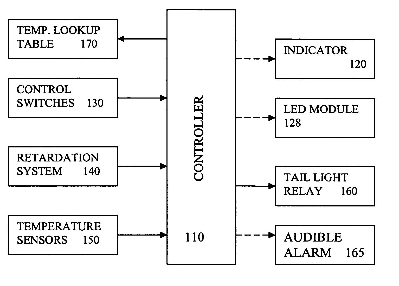
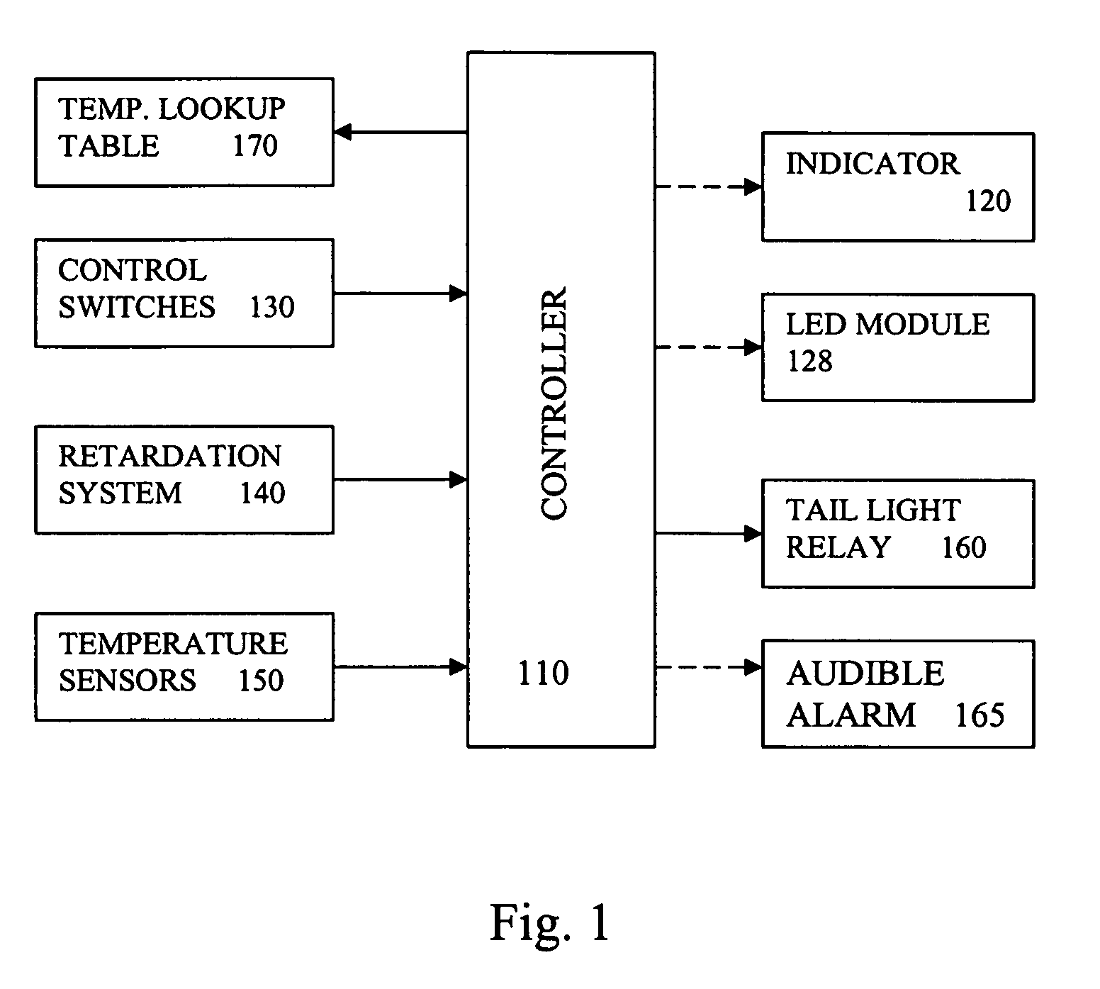
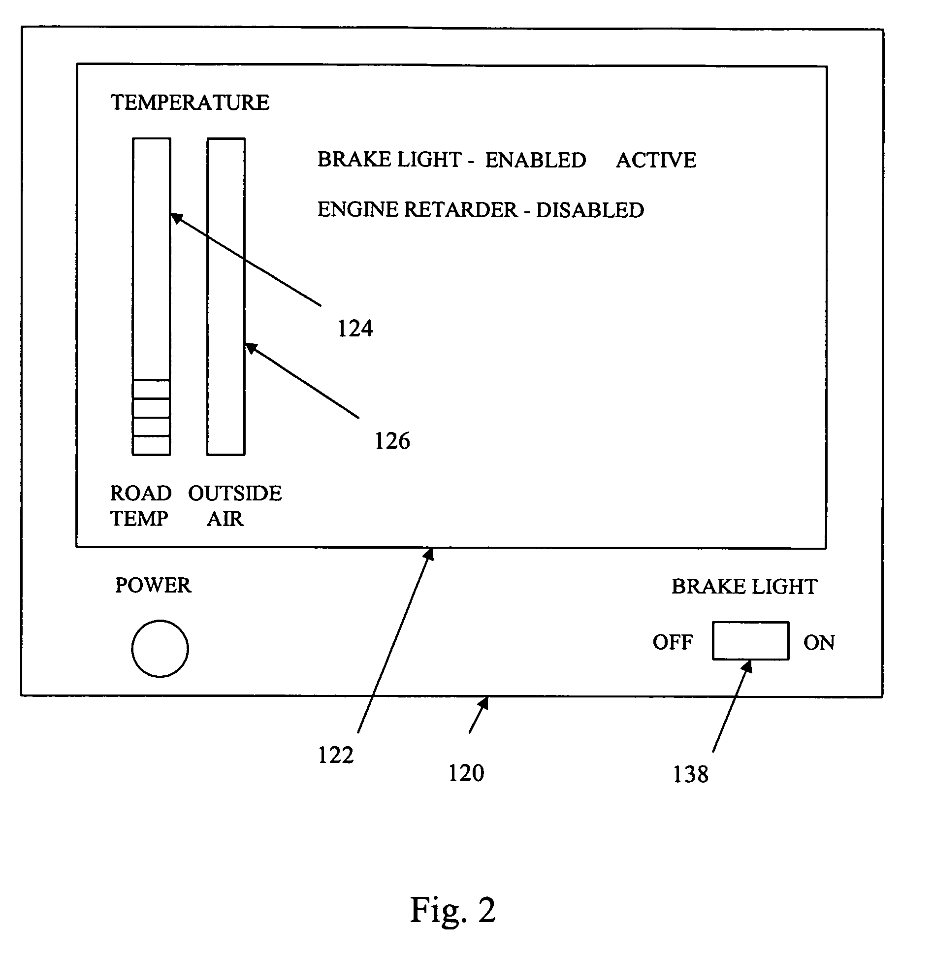
100vehicle warning system110controller120indicator122display screen124road temperature barograph126outside temperature barograph128LED module130controls138brake light switch140retarder data150temperature sensors160brake light relay165audible alarm170temperature lookup table

[0034]FIG. 1 is a block diagram of a vehicle hazard warning system 100 to provide a warning for hazardous road conditions due to cold temperature. The vehicle warning system 100 of the present invention includes a microprocessor-ba...


PUM


Abstract

Apparatus, methods, system and devices for monitoring road surface temperature to detect hazardous road surface conditions. An indicator provides the sensed road surface temperature and hazardous road condition warning to a driver while a tail light interface automatically produce a tail light signal to warn drivers traveling behind the vehicle when a hazardous condition is detected. In an embodiment, the system includes a vehicle engine retardation system interfaced with the hazardous road condition warning system. When the retardation system is in use and hazardous road surface conditions are detected the controller automatically produces the brake light signal unless a tail light control switch is used to manually deactivating the automatic tail light flashing signal when the vehicle is traveling in a state that does not allow alternative control of the brake lights.

Description

FIELD OF THE INVENTION[0001]This invention relates to motor vehicle braking devices and, in particular, to methods, systems, apparatus and devices for monitoring environmental conditions and the motor brake retarders and illuminating the brake lights in response to the monitored environment.BACKGROUND AND PRIOR ART[0002]In most jurisdictions across North America laws have been enacted making it mandatory for a motor vehicle to be equipped with rear brake lights connected to a pedal activated brake. The brake lights are illuminated upon activation of the pedal activated brake. When one motor vehicle is following another, the illumination of the lights of the lead vehicle provides a driver of the following motor vehicle with warning that the lead vehicle is decelerating.[0003]Most large trucks have an auxiliary braking system known as a retardation system. The retardation system is used to slow the vehicle down. The driver does not need to activate the pedal activated brake in order t...

Claims


Application Information

Patent Timeline
IPC IPC(8): G08B19/02G06F17/10G06F7/00G08G1/00G08G1/09B60Q1/26B60Q1/52
CPCB60Q1/46G08G1/163B60Q1/50B60Q1/545
Inventor CHINN, GREGORY F.LAUGHEAD, MICHAELTOMAN, JOHN
Owner OVERLAND SAFETY TECH CORP
Why Eureka
Try Eureka