Image display device and portable terminal device using the same

a portable terminal and display device technology, applied in the direction of optics, projectors, instruments, etc., can solve the problems of reducing the efficiency of using the exterior light, deteriorating display quality, and substantial difficulty in avoiding, so as to prevent the brightness reduction, improve the effect of image quality, and contribute to the display

Active Publication Date: 2007-11-27
NEC LCD TECH CORP
View PDF10 Cites 38 Cited by
  • Summary
  • Abstract
  • Description
  • Claims
  • Application Information

AI Technical Summary

Benefits of technology

[0031]In view of the above-described problems in the prior art, it is an object of the present invention to provide a three-dimensional image display device, which has an excellent display quality without any brightness reduction in the reflection display mode.
[0032]It is another object of the present invention to provide a portable terminal device, using such a three-dimensional image display device, which terminal device ensures high quality of display without any brightness reduction in the reflection display mode.

Problems solved by technology

Because it is substantially difficult to avoid troublesome resulting from the usage of eyeglasses, the methods requiring un-using eyeglasses have been mostly studied in the recent years.
However, in the case when such a reflective display device is used, the flat plane of the reflection plate reflects the exterior light as if it is a mirror, and therefore the other light source, such as a fluorescent light is imaged thereon, so that quality of display is deteriorated.
Moreover, as for an observer, only the light incident from a specific angle contributes to the display, thereby causing the efficiency in using the exterior light to be reduced.
As a result, quality of a three-dimensional image display is deteriorated by the unevenness in the brightness.
That is, if the right eye is positioned within such a range, the right eye receives the light having a sufficient intensity, but the left eye can hardly receive light.
Hence, the brightness is detected in a varied state for respective pixels in the display device, and therefore a three-dimensional image, on which an image having a spatially varied brightness is superimposed, is observed, thereby causing quality of the three-dimensional image display to be deteriorated.
Such a problem generally occurs not only in the three-dimensional image display device but also in the aforementioned display of simultaneously displaying plural images with respect to plural viewpoints.

Method used


Image

  • Image display device and portable terminal device using the same
  • Image display device and portable terminal device using the same
  • Image display device and portable terminal device using the same

Examples


first embodiment

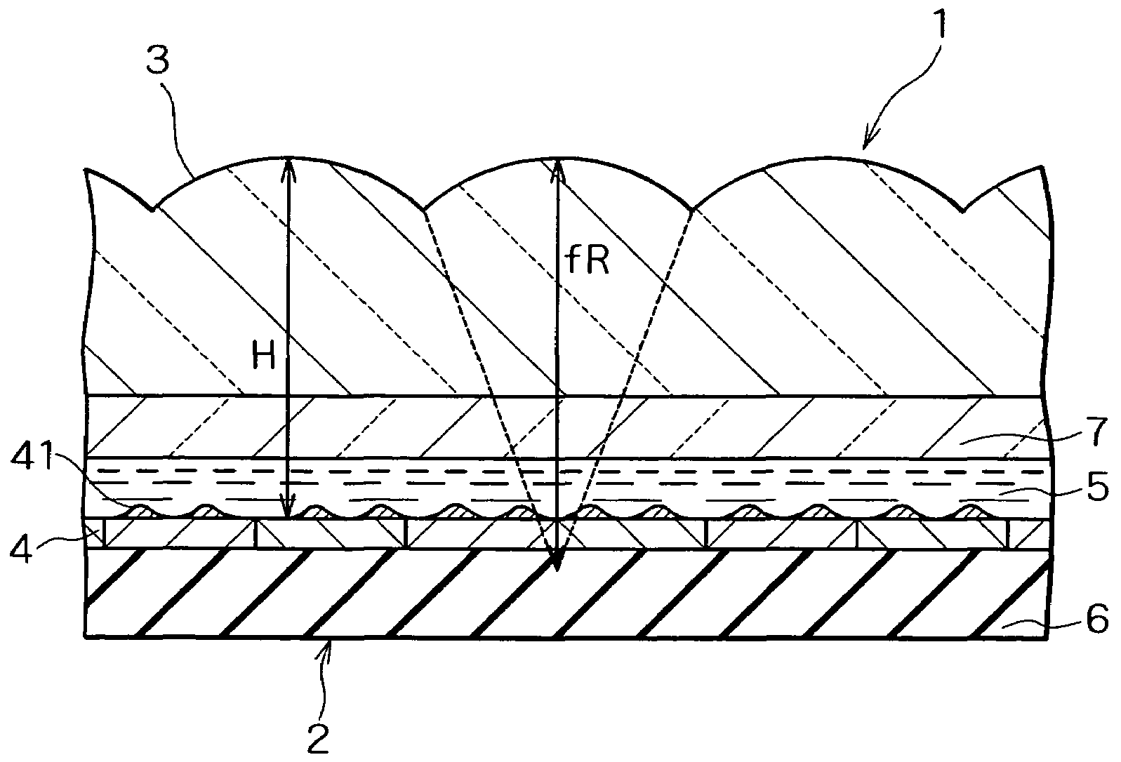
[0091]FIG. 12 is a sectional view of a three-dimensional image display device in a first embodiment of the invention, and FIG. 13 is a perspective view of a portable terminal device in the first embodiment of the invention. The three-dimensional image display device 1 comprises a reflective liquid crystal display panel 2 and a lenticular lens 3. In the reflective liquid crystal display panel 2, a liquid crystal layer 5 is interposed between a base plate 6 and a transparent substrate 7, and a pixel electrode (reflection plate 4) is formed on the liquid crystal layer side surface of the substrate 6, and a counter electrode (not shown) is formed on the liquid crystal layer side surface of the transparent substrate 7. The pixel electrode and counter electrode are stripe-shaped electrodes which are disposed perpendicular to each other. A voltage is applied between the pixel electrode and counter electrode to select a pixel determined at a cross point of these electrodes, and therefore th...

second embodiment

[0108]FIG. 19 is a sectional view of a three-dimensional image display device in a second embodiment of the invention. The second embodiment is different from the first embodiment regarding the following point: The distance HR between the lens surface and the pixel in the second embodiment is designed to be smaller than the distance HR between the lens surface and the pixel in the conventional optical model determined by the above expressions 10 to 12. Accordingly, the distance HR between the lens surface and the pixel in the second embodiment is smaller than the focal distance f of the lenticular lens.

[0109]Regarding the distance HR between the lens surface and the pixel in the second embodiment, it is particularly preferable that the light condensed by the lens illuminates inclined surfaces having different inclination angles, as shown in FIG. 20, because this arrangement provides a wider angular distribution for the reflected light, thus causing a greater amount of the reflected ...

third embodiment

[0112]FIG. 21 is a sectional view of a three-dimensional image display device in a third embodiment of the invention. The focal distance fR of the lenticular lens in the third embodiment is smaller than the focal distance f of the conventional optical model, calculated by the above expressions 10 to 12 and 16, compared with the first embodiment of the invention, and the distance H between the lens surface and the pixel is calculated by the above expressions 10 to 12.

[0113]Regarding the focal distance f in the third embodiment of the invention, it is particularly preferable that the light condensed by the lens illuminates inclined surfaces having different inclination angles, as shown in FIG. 22, because this arrangement provides a wider angular distribution for the reflected light, thus causing a greater amount of the reflected light to proceed toward the observer. Assuming that the pitch of surface projections is V, this condition can be expressed by the following expression 28 fro...


PUM

PropertyMeasurementUnit
distance WPaaaaaaaaaa
distance ODaaaaaaaaaa

Abstract

In a display panel, a plurality of pixel sections are arranged in the form of a matrix. Each of the pixel sections includes a pixel for displaying an image for the left eye and a pixel for displaying an image for the right eye. Lenticular lens having repeated convex surfaces is disposed in front of the display panel to deflect the light emitted from each pixel in the horizontal direction from the pixel for displaying the image for the left eye to the pixel for displaying the image for the right eye in each pixel section. Reflection plate reflects the exterior light toward the display panel and has surface projections on the surface. In this case, the focal distance f of the lens is different from the distance H between the surface of the reflection plate and the apex of the lens.

Description

BACKGROUND OF THE INVENTION[0001]1. Technical Field of the Invention[0002]The present invention relates to an image display device which uses a lens such as a lenticular lens or a fly-eye lens and can display images respectively directed to plural viewpoints and to a portable terminal device using the image display device. More specifically, the present invention relates to an image display device which has an excellent display quality without any brightness reduction in the reflection display mode and to a portable terminal device using the image display device.[0003]2. Description of the Related Art[0004]Since the distant past, various investigations have been made on a display device capable of displaying a three-dimensional image. Regarding the binocular vision, the Greek mathematician, Euclid, stated in 280 B.C. that “the binocular vision is a visual perception which a person can be obtained, simultaneously watching with his own left and right eyes two different images which ar...

Claims


Application Information

Patent Timeline
Patent Type & Authority Patents(United States)
IPC IPC(8): G02F1/1335G02B27/22G03B21/00G03B21/14H04N13/307
CPCG02F1/133526H04N13/0406H04N13/0404G02F1/133553H04N13/305H04N13/307
Inventor UEHARA, SHIN-ICHITAKANASHI, NOBUAKI
Owner NEC LCD TECH CORP
Why Eureka
Try Eureka