
Optical switching device using holographic polymer dispersed liquid crystals

a polymer dispersed liquid crystal and optical switch technology, applied in optics, non-linear optics, instruments, etc., can solve the problems of reducing battery life if constantly used, poor image displayed by reflective lcds, and consuming the most power in lcds, so as to avoid noticeable weight, not easily misaligned or broken

Inactive Publication Date: 2007-11-27
ALPS ELECTRIC NORTH AMERICA
View PDF23 Cites 75 Cited by
  • Summary
  • Abstract
  • Description
  • Claims
  • Application Information

AI Technical Summary

Benefits of technology

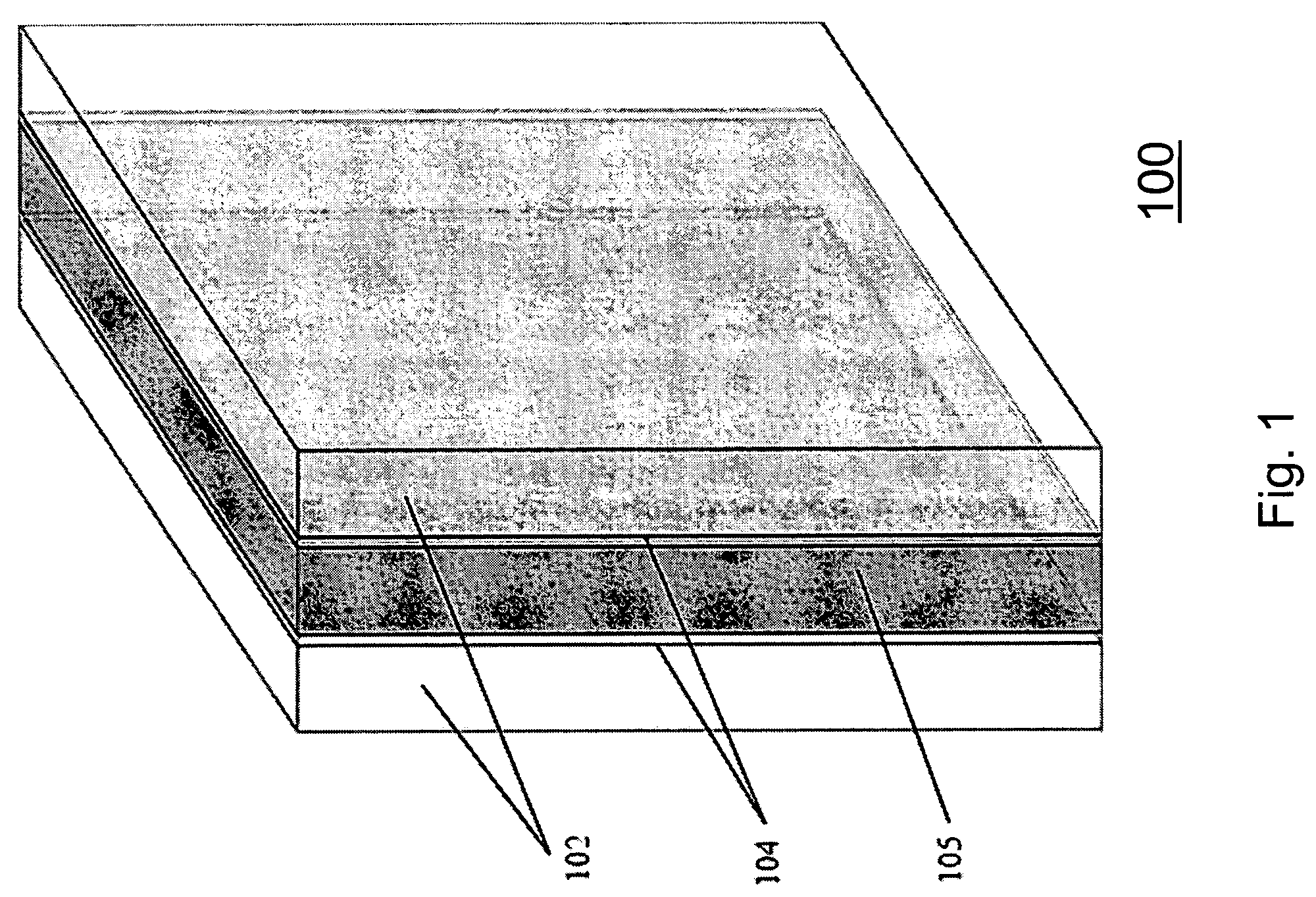
[0008]By way of introduction only, the present embodiments provide an optical switch that may be preferable to use in small electronic devices, in addition to being used elsewhere. The optical switch transmits light from a wideband light source such as a light emitting diode (LED) through the optical switch without application of a voltage to the switch without substantial attenuation over the entire wavelength range of the light source. The switch is compact enough to fit in a camera cellular phone, for example, without adding appreciable size and is light enough to not add noticeable weight. The switch is polarization independent, transmitting and diffracting light of both s and p polarizations without substantial loss. This is to say that materials in the switch that compensate for different polarization such that the switch affects both s and p polarizations of the light from the light source in substantially the same manner independent of a voltage applied to the switch. The switch is also non-mechanical inasmuch as no shutters or other components need be used, thereby affording application of a rugged component that is not easily misaligned or broken if the electronic device is dropped or otherwise subject to a physical shock.

Problems solved by technology

However, if the external light intensity is not strong enough, the image displayed by the reflective LCD is poor.
However, besides increasing the size of the LCD (and adding weight and cost), the backlight also consumes the most power in the LCD, severely decreasing battery life if constantly used.
However, no structure or optical switch exists that provides this ability within the required tolerances of the small electronics, e.g. cost, size, weight, ruggedness, and minimal power consumption.

Method used


Image

  • Optical switching device using holographic polymer dispersed liquid crystals
  • Optical switching device using holographic polymer dispersed liquid crystals
  • Optical switching device using holographic polymer dispersed liquid crystals

Examples


Embodiment Construction

[0023]As described above, in transflective LCDs, the light from the light source is supplied to the LCD through the light guide layer and the transparent substrate of the LCD. Typically, no switch is provided between the light source and the liquid crystal panel. While a mechanical switch could be used, such a switch is relatively bulky and adds considerable weight to the device in which the LCD and switch is housed. Furthermore, the large increase in the size of the LCD, relative fragility (i.e. the switch may easily be broken, become dislodged or become misaligned if the device is dropped or otherwise subject to physical shocks), and large power / current requirements are severe detriments to the use of a mechanical switch. HPDLCs may be integrated in the device to provide switching and alleviate a number of problems. The present HPDLCs dramatically decrease the response time of the switch: a mechanical switch has a typical response time of 10-20 milliseconds, whereas the present HP...


PUM

PropertyMeasurementUnit
wavelengthaaaaaaaaaa
refractive indexaaaaaaaaaa
response timeaaaaaaaaaa

Abstract

A thin holographic optical switch used in a liquid crystal display device contains opposing transparent substrates transparent electrodes between the substrates and a diffraction grating between the electrodes. The diffraction grating contains regions of transparent polymerized photopolymers and cholesteric liquid crystal micro-droplets. Refractive indexes of the photopolymers and liquid crystal are substantially the same when the electrodes have the same potential. The holographic optical switch transmits broadband LED light when the potential difference between the electrodes is zero and is polarization independent. The holographic optical switch diffracts broadband LED light when the potential difference between the electrodes is non-zero and is polarization independent.

Description

BACKGROUND[0001]This invention is related generally to an optical device that can switch the direction of impinging light. More particularly, the present invention is related to a holographic optical switch containing polymer dispersed liquid crystals in liquid crystal displays and other electronics.[0002]Liquid crystal display devices (LCD) have many advantages over other types of displays. LCDs provide high picture quality in a small volume and are lightweight. In addition, LCDs have comparatively low power consumption, which is dependent on the type of LCD. This has caused the portable electronic market to focus on LCD use for such applications as small portable televisions, mobile telephones and other communication products, video recording units, notebook computers, and desktop monitors.[0003]Active LCDs, which are the most common LCDs in use, contain substrates, a liquid crystal layer through which light passes, and a pixel electrode on one of the substrates that supplies an e...

Claims


Application Information

Patent Timeline
Patent Type & Authority Patents(United States)
IPC IPC(8): G02F1/13G02F1/1335G02F1/1334G02F1/13357G02F1/31
CPCG02F1/13342G02F1/31G02F2203/06G02F1/133615
Inventor LIN, JIBINGTANG, SUNINGTANG, YUANJIAIHARA, MASAMI
Owner ALPS ELECTRIC NORTH AMERICA
Learn More