
Apparatus and method of assay in utilizing attenuated total reflection

a total reflection and apparatus technology, applied in the direction of chemical methods analysis, chemical indicators analysis, instruments, etc., can solve the problems of pipette couple method, liquid buffer from exit end opening likely to leak from end, and electric noise in output signal

Inactive Publication Date: 2007-11-27
FUJIFILM CORP +1
View PDF15 Cites 3 Cited by
  • Summary
  • Abstract
  • Description
  • Claims
  • Application Information

AI Technical Summary

Benefits of technology

The present invention provides an apparatus and method for conducting optical assays using attenuated total reflection. The apparatus includes a sensor unit with a transparent dielectric medium and a thin film, a flow channel for introducing sample fluid, and a suction device for draining used sample fluid. The apparatus is designed to protect the flow channel from backflow of waste fluid. The method includes the steps of sucking and draining the sample fluid, using a suction device to prevent backflow. The invention aims to improve the accuracy and efficiency of optical assays by preventing contamination and ensuring reliable measurements.

Problems solved by technology

However, there is a problem in the method of the pipette couple.
After the introduction, the liquid buffer from the exit end opening is likely to leak from the end of the removing pipette upon unloading of the pipette couple.
A backflow of the liquid buffer causes a serious problem in electric noise in an output signal of the assay.

Method used


Image

  • Apparatus and method of assay in utilizing attenuated total reflection
  • Apparatus and method of assay in utilizing attenuated total reflection
  • Apparatus and method of assay in utilizing attenuated total reflection

Examples


Embodiment Construction

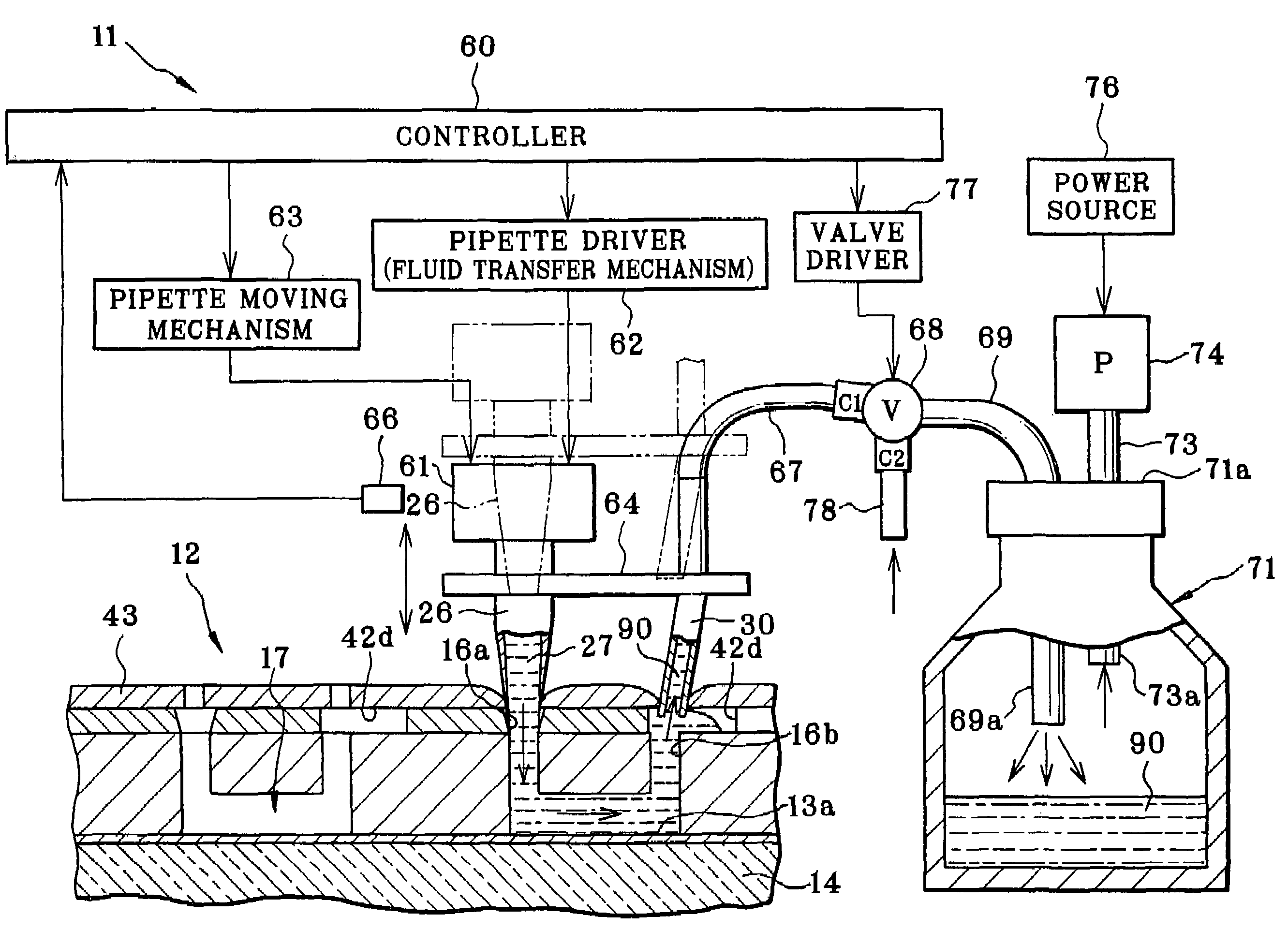
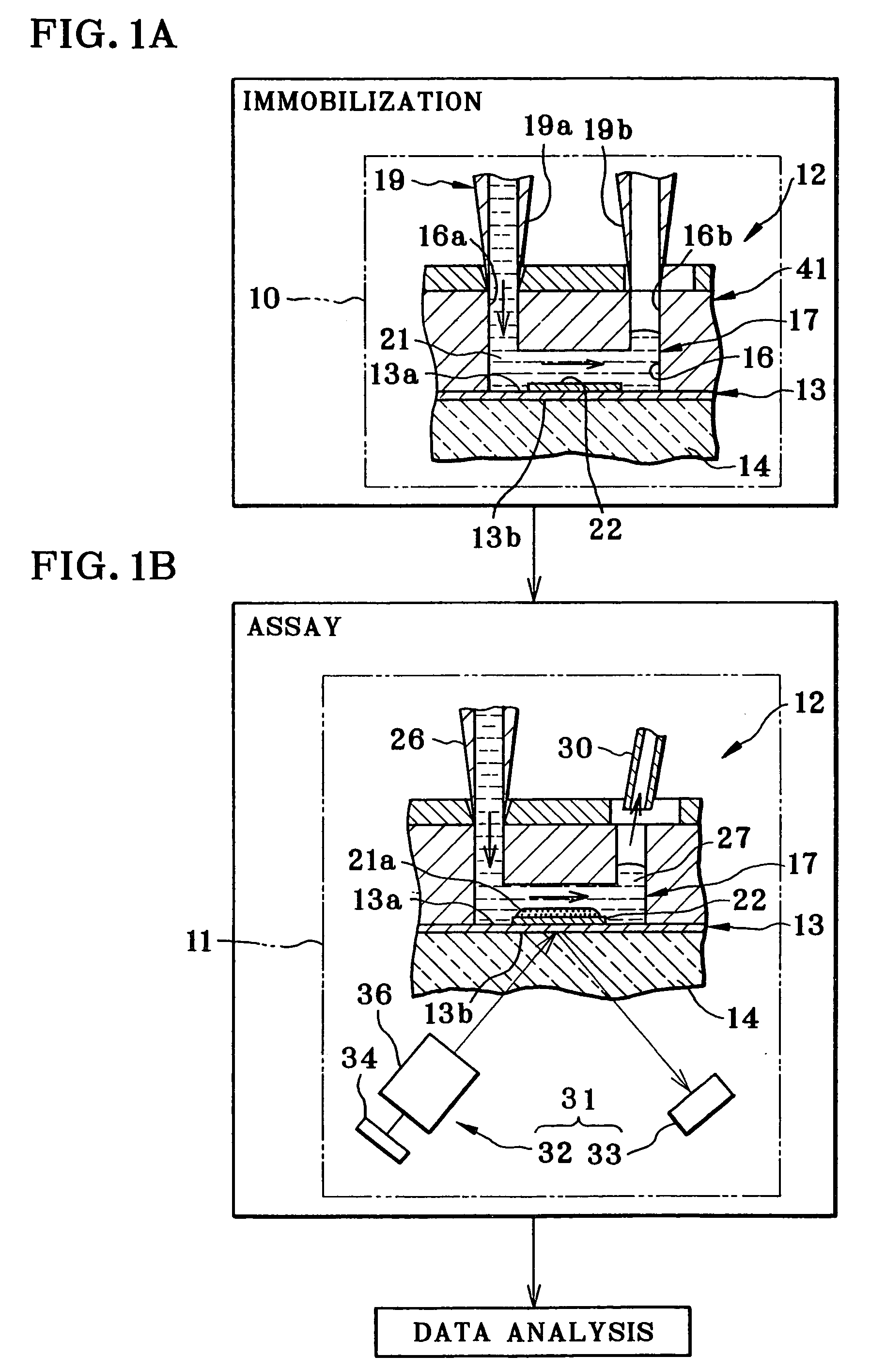
[0037]In FIGS. 1A and 1B, a system for measuring or assay according to SPR (surface plasmon resonance) is illustrated. A sequence of the assay system is constituted by three processes which are a sample immobilizing process, assay process and data analyzing process. The assay system includes a sample immobilizing device 10, an assay apparatus 11, and a data analyzer.

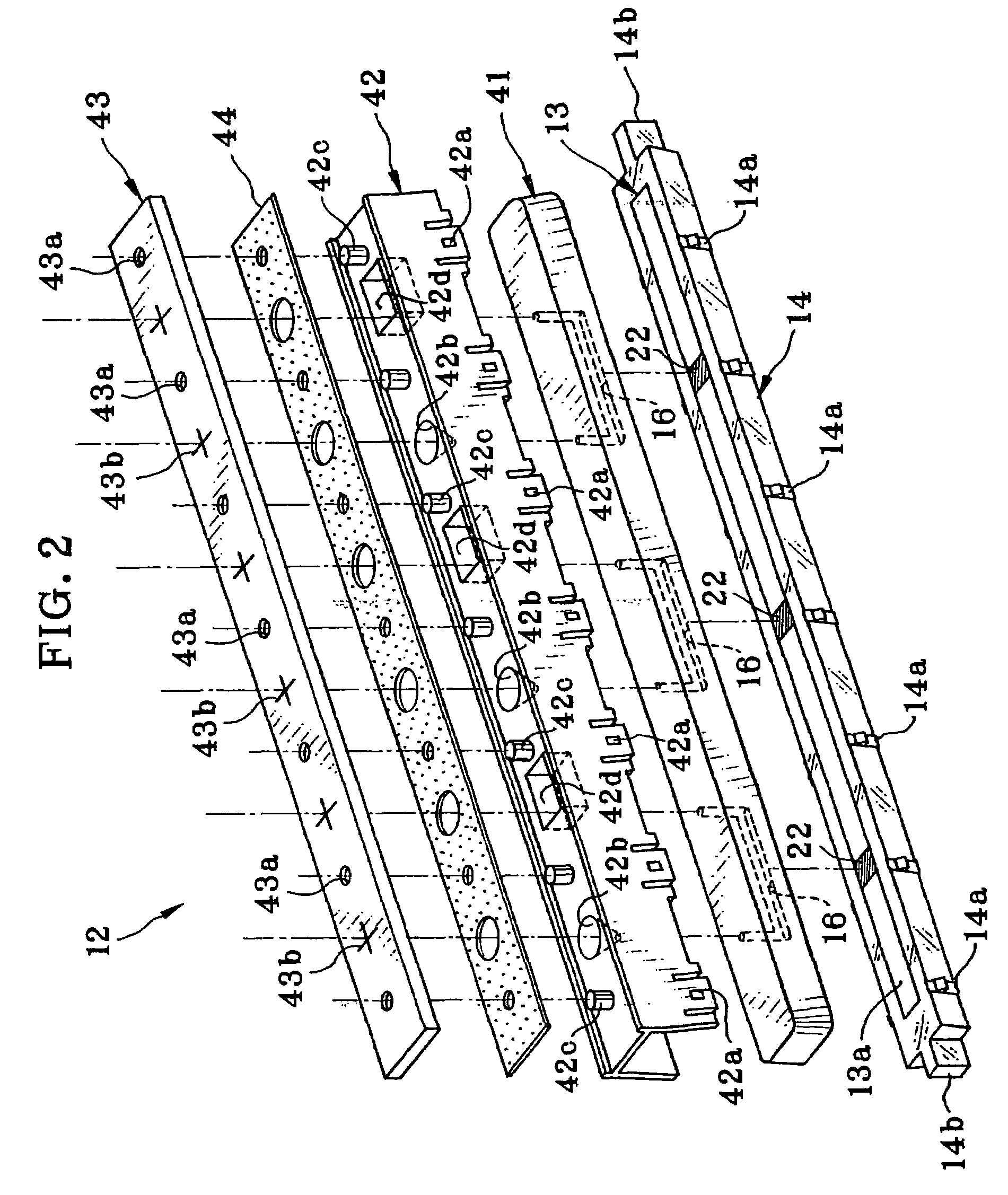
[0038]A surface plasmon resonance (SPR) biosensor is used as a sensor unit 12 for assay. The sensor unit 12 includes a metal film 13, a prism 14 and a flow channel block 41. A first surface of the metal film 13 is a sensing surface 13a where surface plasmon resonance is created. A second surface of the metal film 13 is a thin film / dielectric interface 13b where the prism 14 is overlaid therewith. The flow channel block 41 has a flow channel 16, which extends along the sensing surface 13a, and causes ligand and analyte as fluids to flow.

[0039]An example of material for the metal film 13 is gold (Au). A thickness of the me...


PUM

PropertyMeasurementUnit
thicknessaaaaaaaaaa
diameteraaaaaaaaaa
timeaaaaaaaaaa

Abstract

A surface plasmon resonance (SPR) assay apparatus is loaded with a sensor unit. The sensor unit has a sensing surface and a flow channel, which has an entrance end opening and an exit end opening, and causes analyte fluid introduced through the entrance end opening to flow on the sensing surface. An optical assay unit assays reaction of the analyte fluid on the sensing surface by detecting attenuation of the illuminated light reflected by a thin film / dielectric interface. A fluid dispenser introduces the analyte fluid to the entrance end opening by pipetting. A fluid collecting vessel stores the analyte fluid used and exited from the exit end opening. A drain conduit extends from the exit end opening toward the fluid collecting vessel, for passage of the used analyte fluid. A suction pump drains the used analyte fluid into the fluid collecting vessel through the drain conduit.

Description

BACKGROUND OF THE INVENTION[0001]1. Field of the Invention[0002]The present invention relates to an apparatus and method for assay in utilizing attenuated total reflection. More particularly, the present invention relates to an apparatus and method for assay in utilizing attenuated total reflection, in which a flow channel can be protected from backflow of waste fluid.[0003]2. Description Related to the Prior Art[0004]An assay apparatus in utilizing attenuated total reflection for assaying a sample is known in the field of the biosensor. U.S. Pat. No. 5,313,264 (corresponding to JP-A 4-501462) discloses a surface plasmon resonance (SPR) sensor as a typical example for this assay.[0005]A thin film, or metal film, is formed on a transparent dielectric medium. One surface of the metal film is a sensing surface where reaction of a sample occurs. Another surface of the metal film is a thin film / dielectric interface where light is applied by satisfying a condition of total reflection. The...

Claims


Application Information

Patent Timeline
Patent Type & Authority Patents(United States)
IPC IPC(8): G01N21/55B01L3/02G01N21/27G01N21/41
CPCG01N21/05G01N21/553G01N35/1095
Inventor SHIMIZU, HITOSHI
Owner FUJIFILM CORP
Learn More