Method and apparatus for detecting a radio frequency to which a broadcast receiver is tuned

a radio frequency and receiver technology, applied in the field of radio frequency detection methods and apparatuses, can solve the problem of no alternative ways of identifying data locations or URLs

Inactive Publication Date: 2007-11-27
MICROVISION
View PDF35 Cites 37 Cited by
  • Summary
  • Abstract
  • Description
  • Claims
  • Application Information

AI Technical Summary

Benefits of technology

[0019]The database corresponding to the clicker described above may include Internet addresses or other data locations specific to a particular channel or frequency and a range of times. For example, the listener may become interested in the subject matter of a particular radio advertisement broadcast on a radio channel. According to the invention, the listener activates the clicker, which identifies and stores in memory the frequency to which the radio receiver is tuned and the time the clicker was activated. This information is transmitted to the database, as more fully described below, to identify the Internet address associated with the observed broadcast frequency and time and, hence, the radio advertisement. Thus, an Internet address associated with the time and channel of the broadcast may be determined even though access to the Internet is not available at the time of the broadcast and even though no Internet address is given. Moreover, the device described above allows the listener to essentially perform a search of the Internet without articulating a query and entering it into a search engine.

Problems solved by technology

This becomes problematic, however, when there is no immediate access to a computer connected to the Internet For example, when a radio listener hears a song on the radio and desires more information about it, he must remember the song title and the artist.
Beyond this method, there are no alternative ways of identifying data locations or URLs based upon an observation of a particular product or event.

Method used


Image

  • Method and apparatus for detecting a radio frequency to which a broadcast receiver is tuned
  • Method and apparatus for detecting a radio frequency to which a broadcast receiver is tuned
  • Method and apparatus for detecting a radio frequency to which a broadcast receiver is tuned

Examples


Embodiment Construction

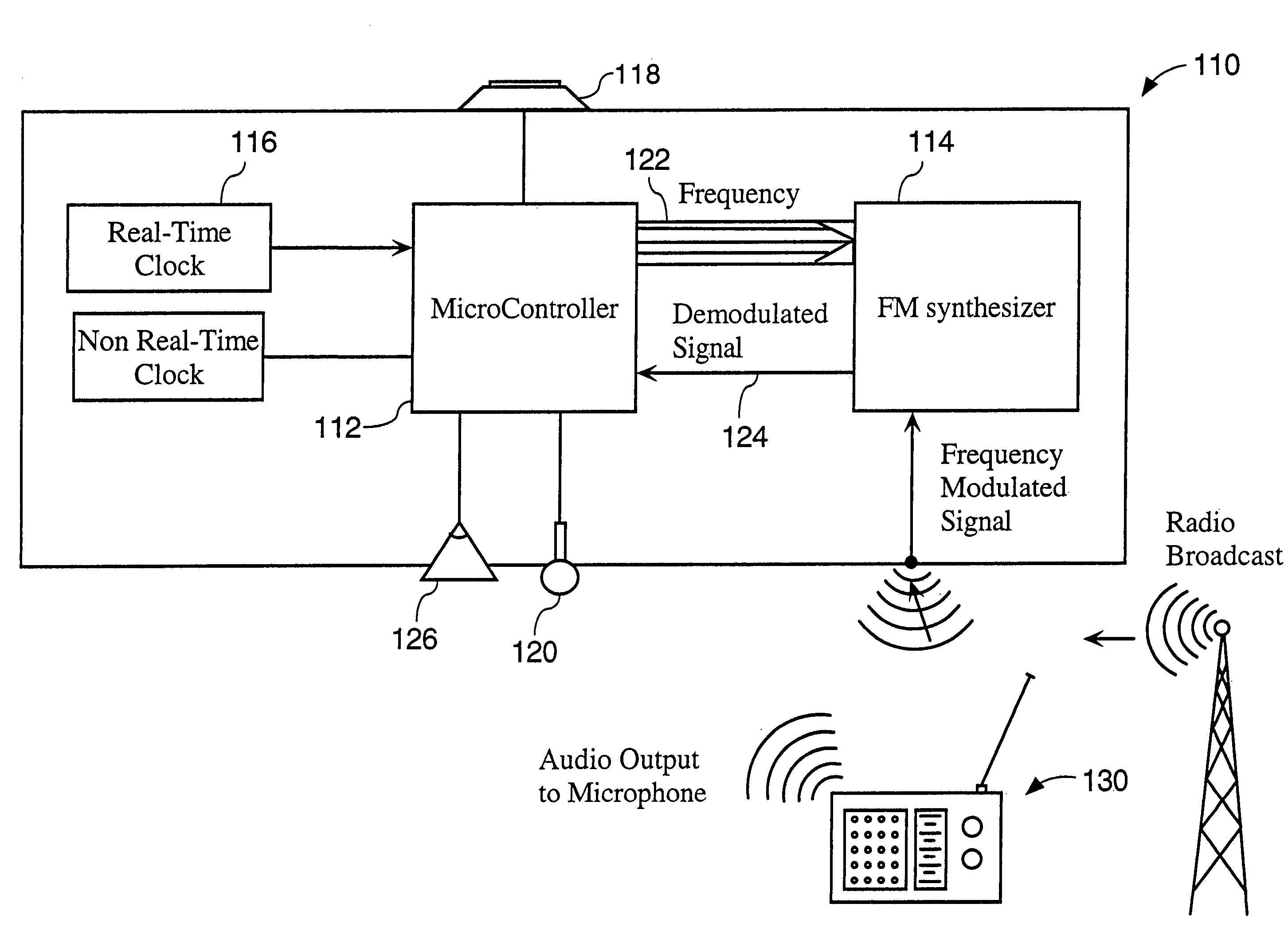
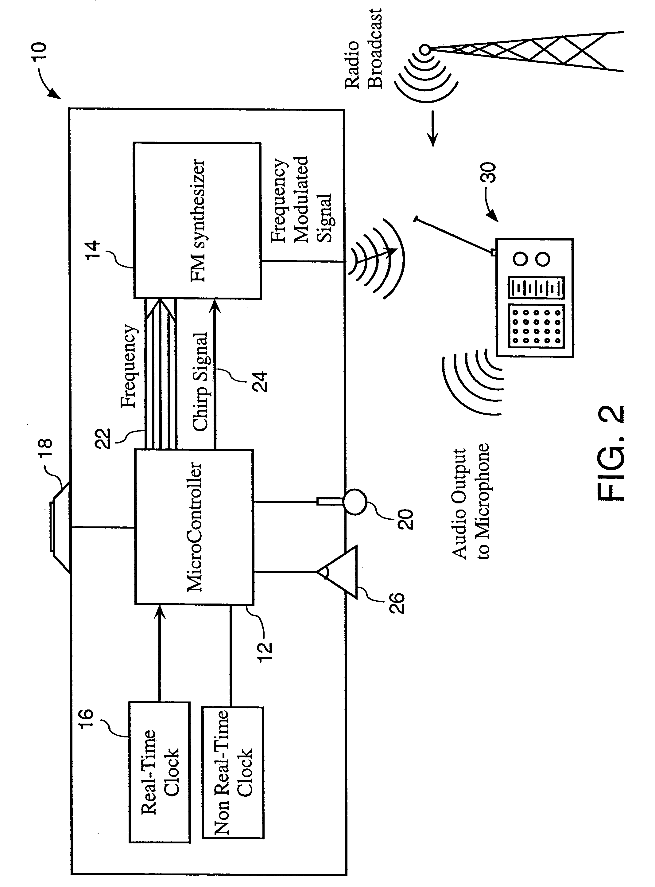
[0033]As discussed above, the present invention provides methods and apparatuses for identifying a data location based upon physical observations in the real world. The method and system generally include identifying one or more physical parameters corresponding to physical observations of real world objects or events and associating such physical parameters with data locations. Another aspect of the present invention identifies data locations based upon physical observations. The method of this aspect of the present invention generally comprises sensing physical parameters associated with physical objects or events and transmitting the observed physical parameters to a database, which includes associations between these physical parameters and one or more data locations.

[0034]The present invention is applicable to the radio broadcast context. According to the invention, a radio listener is provided with a frequency sensing unit, which the listener activates when he / she hears a song...


PUM


Abstract

A method and apparatus is disclosed for detecting the frequency to which a broadcast receiver is tuned. In one embodiment, a sensing unit emits a chirp signal over a range of broadcast bands and monitors the output of the radio receiver to detect the frequency to which the radio receiver is tuned. In another embodiment, a sensing unit demodulates radio signals across a range of frequencies and compares the demodulated signals to observed audio output of the radio receiver.

Description

[0001]This is a division of application Ser. No. 09 / 559,031, filed Apr. 27, 2000 now U.S. Pat. No. 6,650,877.RELATED APPLICATION[0002]The present application is a continuation-in-part of U.S. application Ser. No. 09 / 303,021, filed Apr. 30, 1999 now U.S. Pat. No. 6,674,993 and entitled “Method and System for Identifying Data Locations Associated with Real World Observations.”FIELD OF THE INVENTION[0003]The present invention relates to a method and system for sensing physical parameters corresponding to an object or event in the physical world and, based on the observed physical parameters, retrieving a data location on a computer network pointing to information associated with the physical world object or event.BACKGROUND OF THE INVENTION[0004]The increasing use of wide area networks such as the Internet has resulted in an explosion in the provision of on-line services. Computer users can access a vast wealth of information and services by utilizing a wide area network to establish a...

Claims


Application Information

Patent Timeline
Patent Type & Authority Patents(United States)
IPC IPC(8): H04Q7/20G06F17/30
CPCG06F17/30876G06F17/3087G06F16/9537G06F16/955
Inventor TARBOURIECH, PHILIPPE
Owner MICROVISION
Why Eureka
Try Eureka