Wheel lift identification for an automotive vehicle

Active Publication Date: 2007-11-27
FORD MOTOR CO
View PDF228 Cites 26 Cited by
  • Summary
  • Abstract
  • Description
  • Claims
  • Application Information

AI Technical Summary

Benefits of technology

[0012]One advantage of the invention is that in vehicles employing a dynamic stability control system, additional sensors may not be required.
[0013]Other objects and features of the pre

Problems solved by technology

Typically, the dynamic control systems do not address roll of the vehicle.
One drawb

Method used


Image

  • Wheel lift identification for an automotive vehicle
  • Wheel lift identification for an automotive vehicle
  • Wheel lift identification for an automotive vehicle

Examples


Embodiment Construction

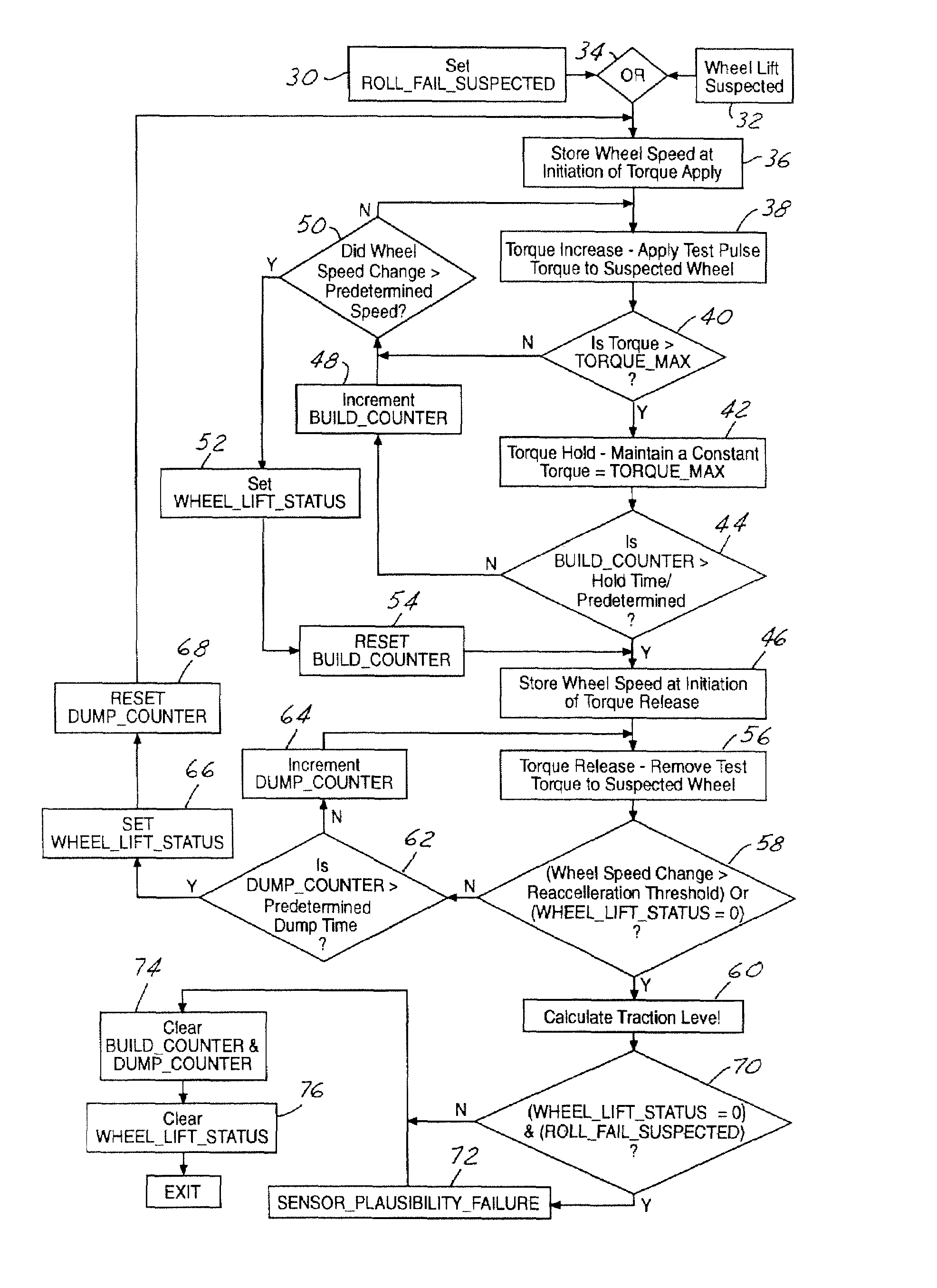
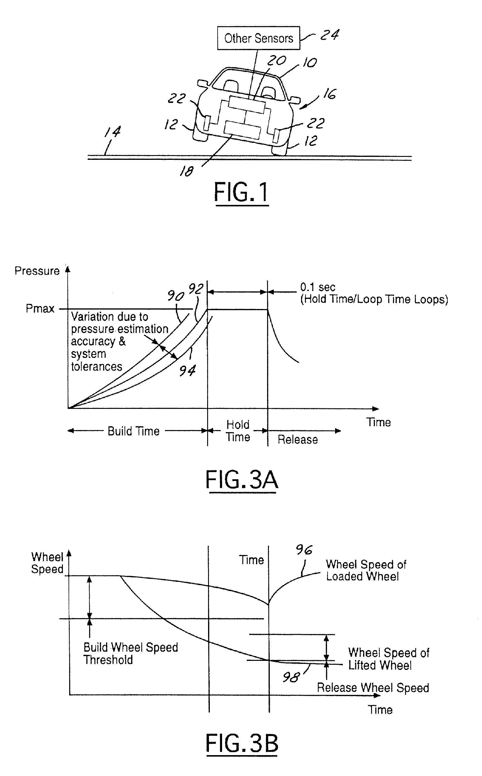
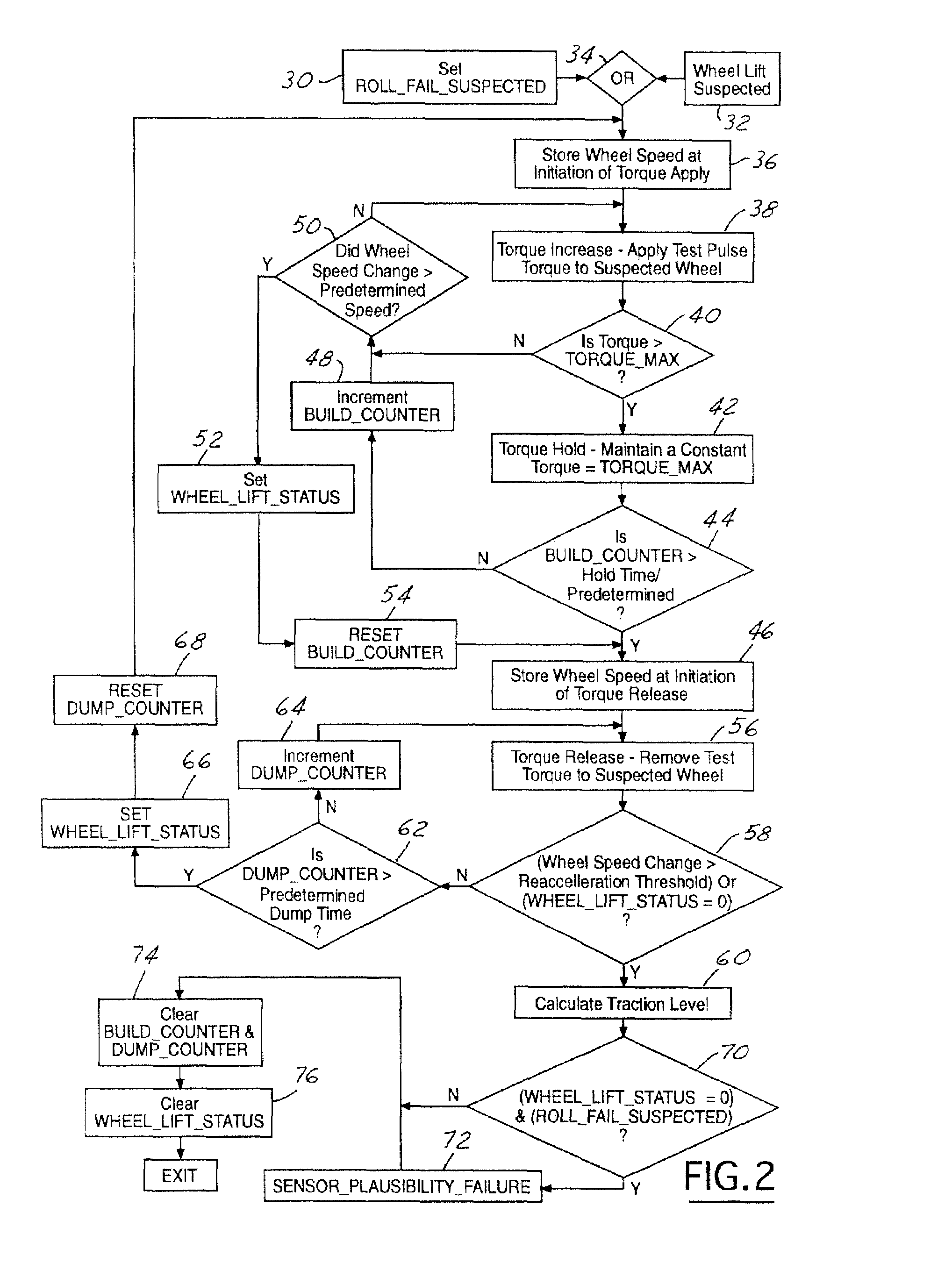
[0023]The present invention is described with respect to a wheel lift identification system for an automotive vehicle. Those skilled in the art will recognize that the present invention may be incorporated into a rollover prevention system for an automotive vehicle.

[0024]Referring now to FIG. 1, an automotive vehicle 10 has a plurality of wheels 12, two of which are shown as elevated above a road plane 14. A roll control system 16 is included within vehicle 10. The roll control system 16 is used to counteract the lifting of wheels 12 from road plane 14 as will be further described below. Roll control system 16 includes a roll controller 18 that is preferably microprocessor based. Roll controller 18 may be part of a dynamic stability control system of the automotive vehicle 10. Roll controller 18 is coupled to a torque control system 20 that is used to control the torque of the wheels 12. Although torque control system 20 is illustrated as a separate item, torque control system 20 ma...


PUM


Abstract

A roll control system (16) for an automotive vehicle (10) is used to detect if one of the plurality of wheels (12) is lifted. The system generates a pressure request to determine if the wheel has lifted. A roll control pressure request may also be generated. The wheel lift pressure is suppressed in response to the roll control pressure request. The system may also store a peak wheel speed after the initiation of a build cycle so that the peak wheel speed is used in the wheel lift determination. Also, the system may have an ABS monitor mode which uses the build and release cycles of the ABS system to determine whether a wheel has lifted.

Description

CROSS REFERENCE TO RELATED APPLICATIONS[0001]The present application is a continuation-in part of U.S. application Ser. No. 10 / 608,909, filed Jun. 27, 2003, and provisional applications 60 / 401,309 filed Aug. 5, 2002, 60 / 400,156 filed Aug. 1, 2002, and 60 / 401,418 filed Aug. 5, 2002, which are incorporated by reference herein.BACKGROUND OF INVENTION[0002]The present invention relates generally to a dynamic behavior control apparatus for an automotive vehicle, and more specifically, to a method and apparatus for determining whether a wheel of an automotive vehicle has lifted from the pavement or become grounded after being lifted from the pavement.[0003]Dynamic control systems for automotive vehicles have recently begun to be offered on various products. Dynamic control systems typically control the yaw of the vehicle by controlling the braking effort at various wheels of the vehicle. By regulating the amount of braking at each corner of the vehicle, the desired direction of the vehicl...

Claims


Application Information

Patent Timeline
IPC IPC(8): B60T8/32B60T8/84B60B39/00G06F17/00B60G17/016B60G17/0195B60R16/02B60R16/023B60R21/00B60R21/01B60R21/0132B60T8/172B60T8/1755B60T8/24B60W30/04
CPCB60G17/0162B60R16/0233B60R21/013B60R21/0132B60T8/172B60T8/17551B60T8/243B60G17/0195B60W30/04B60G2800/0194B60G2800/215B60G2800/922B60R2021/0018B60R2021/01327B60T2230/03B60T2240/06
Inventor MEYERS, JOSEPH CARRBROWN, TODD ALLEN
Owner FORD MOTOR CO
Why Eureka
Try Eureka