Automatic mapping logic for a combustor in a gas turbine engine

a technology of automatic mapping and gas turbine engine, which is applied in the ignition of turbine/propulsion engine, instruments, lighting and heating apparatus, etc., can solve the problems of increasing the money and time cost of the combustor mapping process, tedious and time-consuming combustor mapping, and the potential of human error

Active Publication Date: 2007-11-27
GENERAL ELECTRIC CO
View PDF8 Cites 27 Cited by
  • Summary
  • Abstract
  • Description
  • Claims
  • Application Information

AI Technical Summary

Problems solved by technology

As a result, combustor mapping is tedious, and time consuming, with the potential of human error.
This training increases the money and time cost of the combustor mapping process.

Method used


Image

  • Automatic mapping logic for a combustor in a gas turbine engine
  • Automatic mapping logic for a combustor in a gas turbine engine
  • Automatic mapping logic for a combustor in a gas turbine engine

Examples


Embodiment Construction

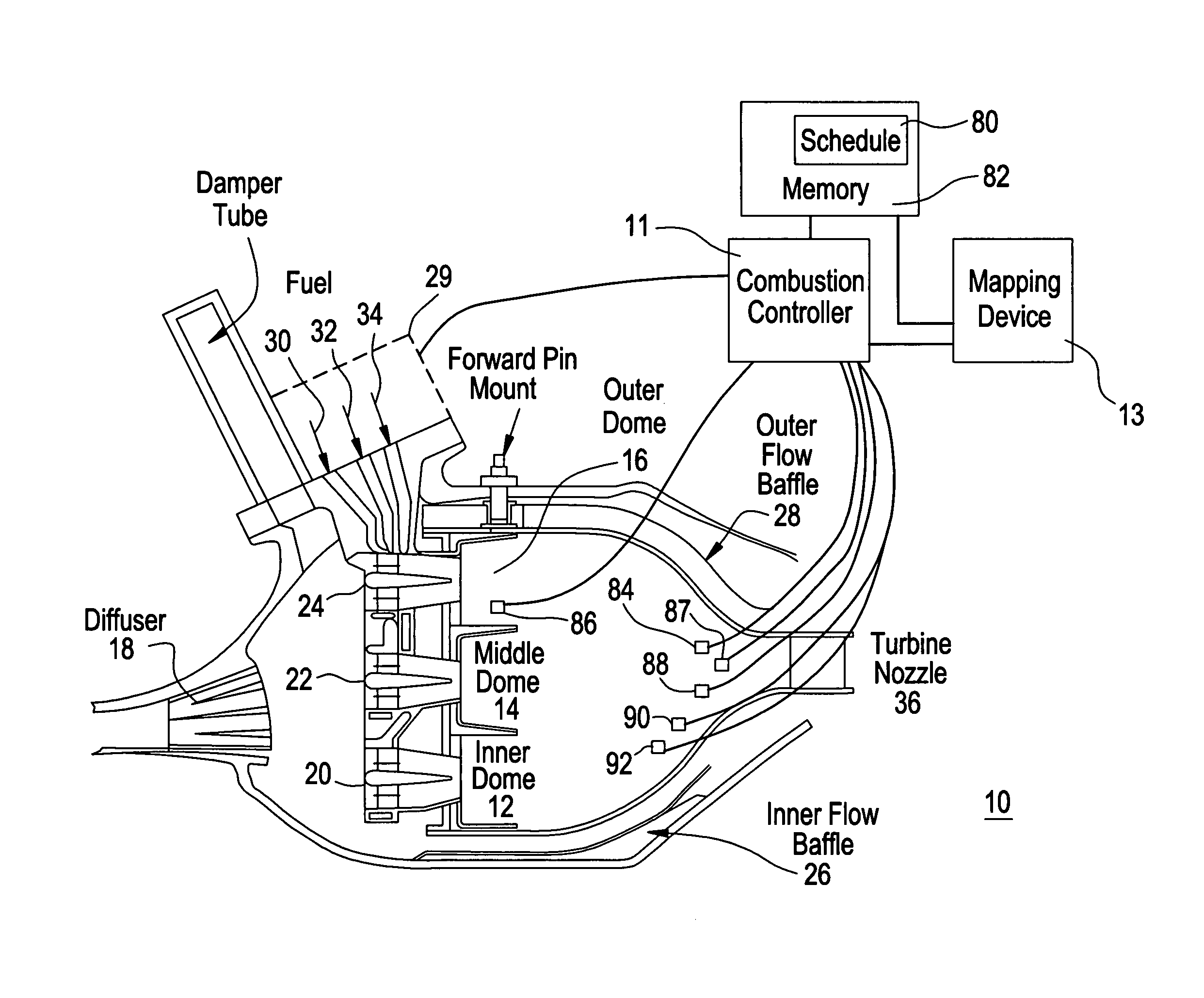
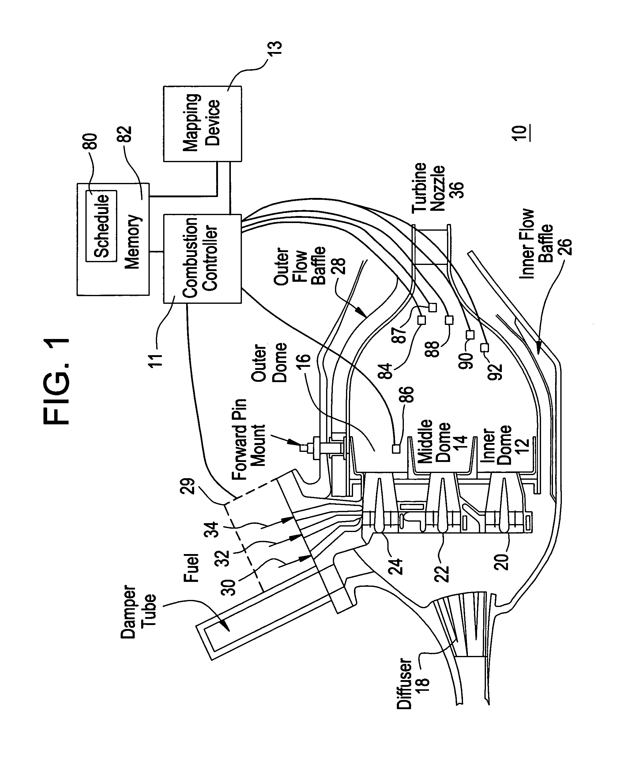
[0018]FIG. 1 shows a cross section of a DLE combustor, generally shown as 10, along with a controller 11 and a mapping device 13. The combustor 10 has three domes (rings) 12, 14, 16 arranged radially to permit parallel staging of the three domes 12, 14, 16. Air enters the combustor 10 via a diffuser 18, where it then passes to a plurality of premixers 20, 22, 24 in the inner, middle and outer domes 12, 14, 16 and to inner and outer flow baffles 26, 28. Air flow in the combustor is controlled by a compressor bleed system (not shown). The middle and outer domes 14, 16 may each consist of 30 premixers 22, 24, while the inner dome 12 may have 15. Pressurized fuel from a fuel delivery system 29 enters the combustor at ports 30, 32, 34 and is injected through holes in each premixer 20, 22, 24, where the air and fuel mix for combustion. After the air / fuel mixture is burned, high-pressure combustion gases exit via turbine nozzle 36.

[0019]Controller 11 provides control signals to the fuel de...


PUM


Abstract

A mapping device maps each burner mode at various bleed settings to generate control schedules for a combustion controller that ensure combustion dynamic (acoustic) pressures, and emissions limits and ring flame temperatures are within operational limits. In general, a method of combustor mapping involves adjusting the bulk ring flame temperature to meet emissions and acoustic requirements. The dome (ring) ring flame temperature is then adjusted to determine maximum and minimum ring flame temperature boundary limits. At both the maximum and minimum ring flame temperatures, the emissions levels and acoustic pressures are checked to see that they are within specification limits. If they are not, the bulk ring flame temperature is adjusted, and the entire process is repeated for that bleed setting and burner mode. If the emissions levels and acoustic pressures are within specification limits, then the power is increased to a different mode and bleed setting combination, and the process is again repeated. During each of these steps, mapping data are recorded.

Description

BACKGROUND[0001]Gas turbines are commonly used as a power source to drive electrical generating equipment (such as in an electrical power station) or for propulsion (e.g., for aircraft, marine vessels, or military equipment such as tanks). A combustion type gas turbine has a gas path, which typically includes, in a serial-flow relationship, an air intake (or inlet), a compressor, a combustor, a turbine, and a gas outlet (or exhaust nozzle). A controller governs the operation of the turbine. The controller includes a processor for generating control signals in response to a plurality of turbine operating conditions. Control of the power generated by the gas turbine is typically exercised through control of fuel flow and airflow into the combustor.[0002]Modern gas turbine engines employ a gas-fired (“lean”) premixed combustion system, known as a Dry Low Emissions (DLE) combustion system. DLE combustion systems are designed to reduce the emissions of nitrous-oxides (NOx), carbon monoxi...

Claims


Application Information

Patent Timeline
Patent Type & Authority Patents(United States)
IPC IPC(8): G06F19/00G06G7/00F23R3/00F02C9/00F02C9/28
CPCF02C9/28
Inventor HOOK, RICHARD BRADFORDKRESS, ERIC JOHNBARROW, WILLIAM LEEBOLTON, JOHN
Owner GENERAL ELECTRIC CO
Why Eureka
Try Eureka