Flow rate-measuring device

a flow rate and measurement device technology, applied in measurement devices, volume/mass flow measurement, instruments, etc., can solve the problems of unsatisfactory function, unsteady flow, drift or involving vortex, etc., and achieve high accuracy and reliable flow measurement. , the effect of suppressing the turbulence of the flow ra

Active Publication Date: 2007-12-04
ORMON CORP
View PDF18 Cites 9 Cited by
  • Summary
  • Abstract
  • Description
  • Claims
  • Application Information

AI Technical Summary

Benefits of technology

[0006]In view of the problems above, it is an object of the present invention to provide a flow measurement device which is able to suppress the turbulence of the flow rate in the cross section of the flow path and conduct high accurate and reliable flow measurement.
[0010]According to the present invention, since the flow sensor is provided on the wall of the flow path in which the fluid to be measured and the member having minimal cross-section flow path is provided at the downstream side of the flow sensor, there is a advantage that it is possible to suppress the turbulence of the flow rate in the cross section of the flow path and conduct high accurate and reliable flow measurement.

Problems solved by technology

However, the real fluid does not always present such a steady flow and has different direction and magnitude of flow at each position of the cross section of the flow path, causing drift or involving vortex (unsteady flow).
However, even in the flow measurement of the above patent document in which the plurality of straightening meshes 103 and the reduced portion 105 are provided, their functions are not sufficiently performed and the flow is not perfectly straightened.

Method used


Image

  • Flow rate-measuring device
  • Flow rate-measuring device
  • Flow rate-measuring device

Examples


Embodiment Construction

[0033]Embodiments of the present invention will be described hereinafter with reference to the accompanying drawings.

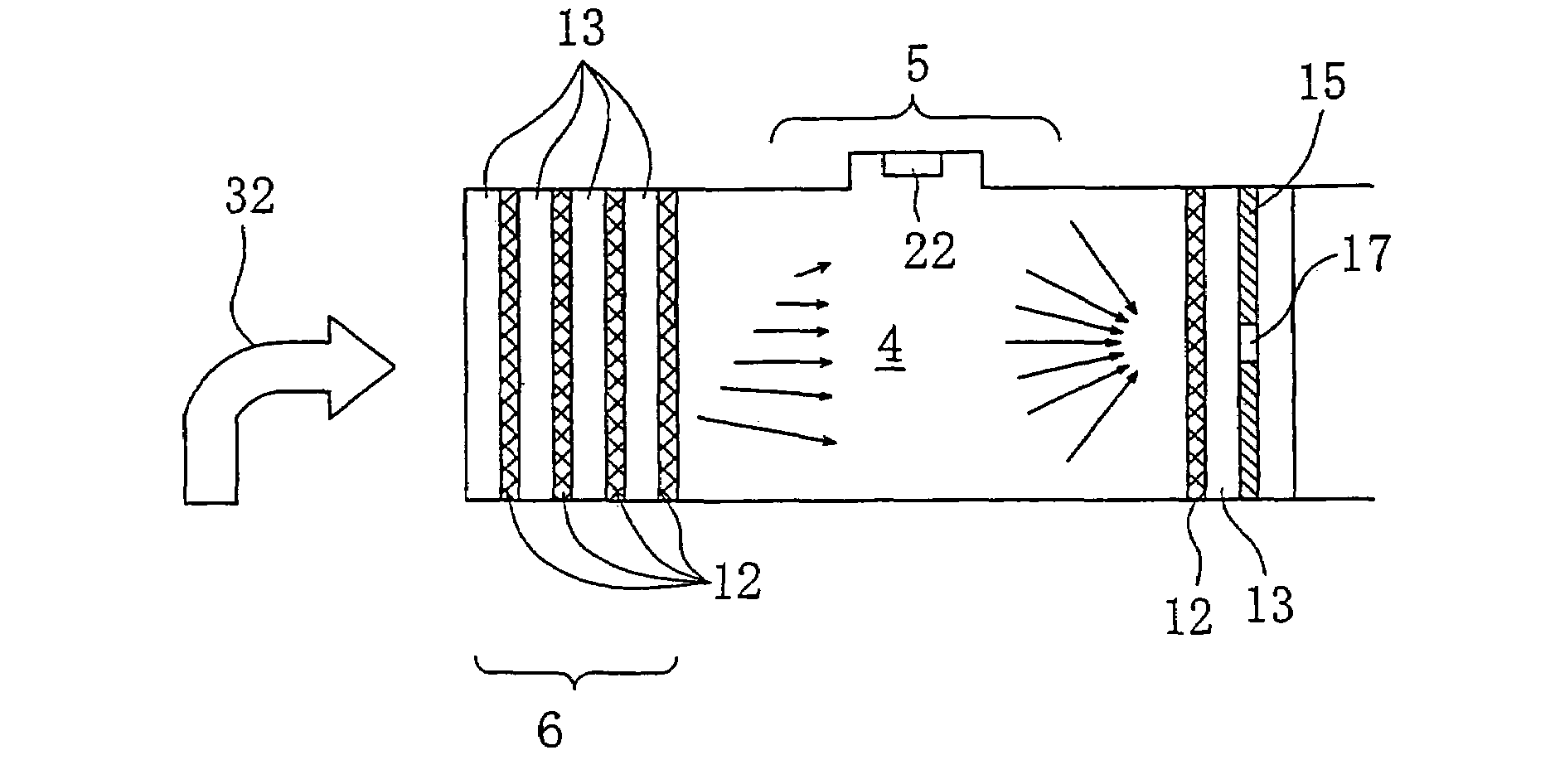
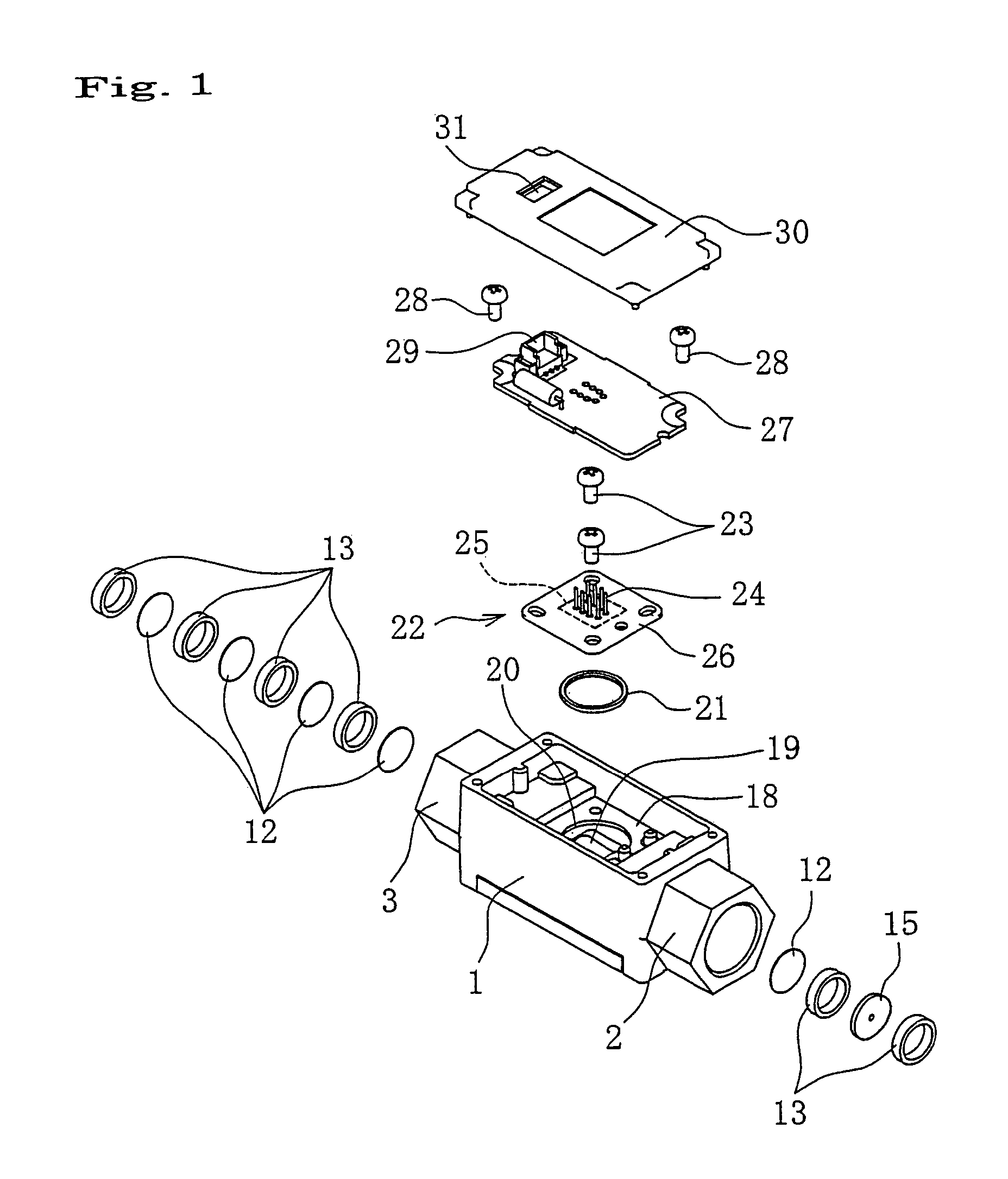
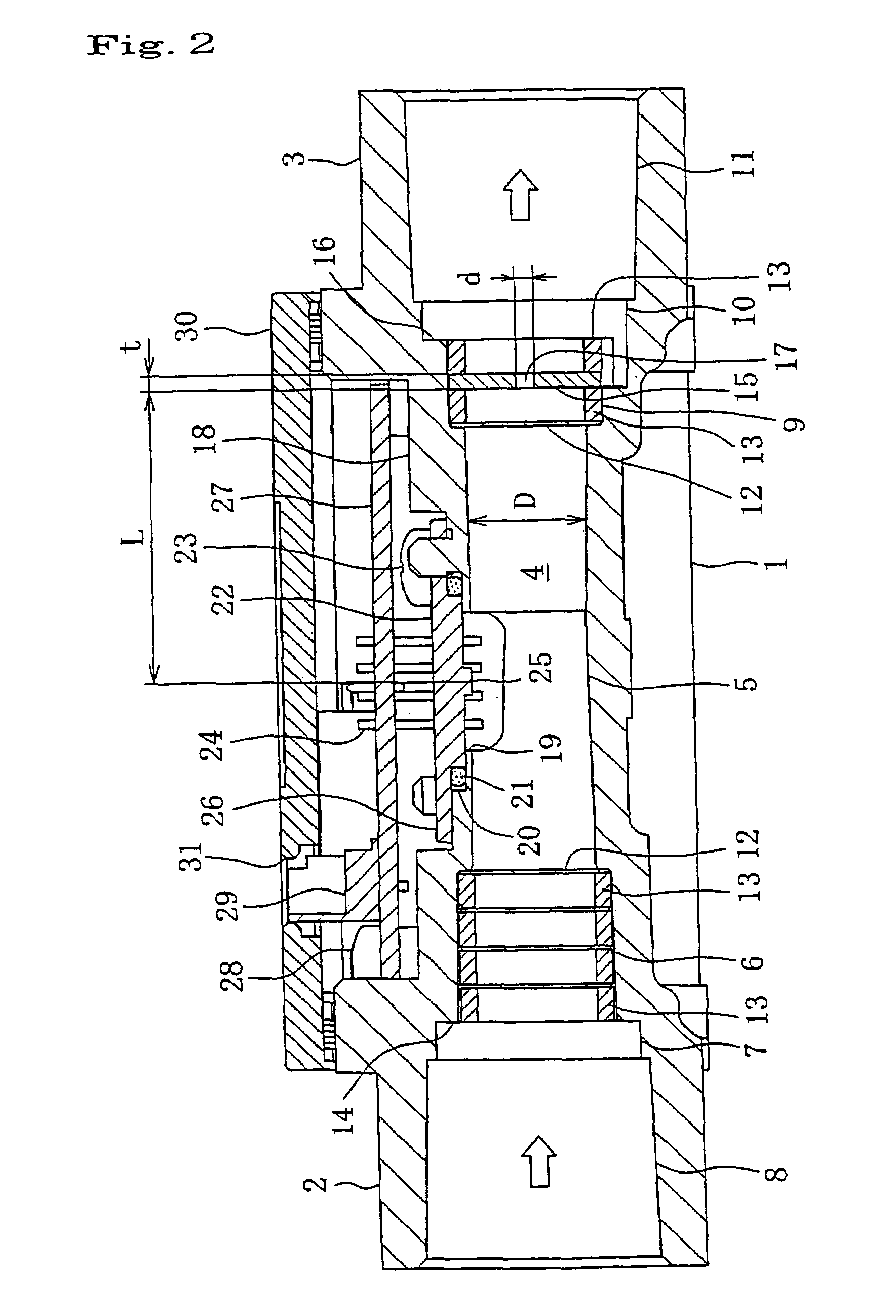
[0034]FIG. 1 is an exploded perspective view of the flow measurement device according to the present invention and FIG. 2 is a sectional view thereof. A base 1 has a parallelepiped and made of resin or metal or so. On the both ends, connecting portions 2, 3 in the form of hexagonal nut are integrally formed to protrude from the both ends. Inside the base 1, a flow path 4 passing through in a longitudinal direction is formed. The cross section of the flow path is circular in the present embodiment but should not be limited to this and any shape such as rectangular or so can be adopted.

[0035]The flow path 4 of the base 1 is formed with a main flow path portion 5 positioned centrally. On the upstream side of the main flow path 5, a straightening portion 6 having a larger diameter than the main flow path 5, a caulking portion 7 having a larger diameter than the straighten...


PUM


Abstract

A flow sensor 22 is provided on a wall surface of a flow path 4 in which a fluid to be measured. A member having minimal cross-section flow path 17 which has a diameter extremely smaller than that of the flow path 4 where the flow sensor 22 is provided is disposed at the downstream of the flow sensor 22.

Description

TECHNICAL FIELD[0001]The present invention relates to a flow measurement device for measuring flow rate of fluid flowing in a flow path.BACKGROUND ART[0002]In a conventional flow measurement device, a flow sensor is attached on the upper part of the wall surface of a flow path formed in a body. On the upstream side of the flow sensor, a plurality of straightening meshes is disposed via spacers at constant intervals. On the downstream side of the flow sensor, a mesh is also disposed. The flow sensor is disposed so that the detector plane of the flow sensor faces the flow path. The flow sensor calculates a flow rate based on a voltage corresponding to a flow velocity of the fluid to be measured and outputs it.[0003]It is ideal that the fluid flowing in the flow path of the flow measurement device presents a uniform flow (steady flow) in which direction and magnitude of flow are same at any positions in the cross section of the flow path. However, the real fluid does not always present...

Claims


Application Information

Patent Timeline
Patent Type & Authority Patents(United States)
IPC IPC(8): G01F1/37G01F1/00G01F1/68G01F1/684G01F15/00
CPCG01F1/684G01F15/00G01F1/6842G01F1/00G01F1/68
Inventor FUJIWARA, TOSHIMITSUNOZOE, SATOSHIKURIBAYASHI, HIDENARI
Owner ORMON CORP
Why Eureka
Try Eureka