Actuation device

a technology of actuating device and actuator, which is applied in the direction of mechanical equipment, mechanical energy handling, transportation and packaging, etc., to achieve the effects of low design effort, economic production, and operational reliability

Inactive Publication Date: 2007-12-04
SCHAEFFLER TECH AG & CO KG
View PDF12 Cites 6 Cited by
  • Summary
  • Abstract
  • Description
  • Claims
  • Application Information

AI Technical Summary

Benefits of technology

[0004]The object of the present invention is to provide an actuating apparatus that can be economically produced and is operationally reliable with little design effort. According to a special aspect, the invention is based on the objective of creating a motor vehicle transmission having an actuating apparatus that can be economically produced and can be actuated in an operationally reliable manner with low design cost and to create an operationally reliable method for control of gear change operations and clutch operations in a drive train of a motor vehicle.SUMMARY OF THE INVENTION
[0011]This enables the relative axial displacement between the positioning device and the drive shaft to be limited in order to entrain the positioning device in the rotational direction upon reaching the maximum displacement when the drive shaft turns in the first rotational direction. Advantageously, a limitation of the axial displacement of the positioning device in relation to the drive shaft may be accomplished using a stop, so that when the drive shaft is driven, the control element is first displaced axially up to the stop and then is entrained by the drive shaft. To ensure this movement sequence, it may be advantageous to provide a braking device, such as a frictional device that acts in the circumferential direction, a slip clutch or the like, on the control element or on another component connected thereto in a non-rotatable manner, the braking force of the braking device being greater than a frictional force that occurs between the drive shaft and positioning device during rotation, thereby ensuring that first an axial displacement of the positioning device occurs and then an entrainment of it occurs in the rotational direction.
[0014]In an advantageous exemplary embodiment, in particular, an actuating apparatus is proposed having a drive shaft that is rotatably mounted, said drive shaft being movable about its longitudinal axis in both rotational directions, namely in a first rotational direction and a second rotational direction opposite the first, and having a nut / threaded spindle assembly that has a threaded spindle and a nut whose thread engages the thread of the threaded spindle, it being possible for the part of this nut / threaded spindle assembly, that faces or is closer to the drive shaft in the power flow, that is, the threaded spindle or the nut, to be rotationally driven by the drive shaft, and the other part of the nut / spindle assembly, that is, the nut or the threaded spindle, being coupled to a positioning device, especially fixedly coupled, so that the axial position of the positioning device that is designed in particular in the direction of the longitudinal axis of the nut or the threaded spindle may be changed, a stop being provided that limits the axial mobility of the positioning device in the one orientation of the axial direction and it being possible to run up against the stop via turning of the drive shaft in a first rotational direction, and this stop causing the positioning device to be moved in an essentially purely rotary or swiveling manner after the stop is reached and the drive shaft continues its rotary movement in the first rotational direction, and the positioning device being designed in a rotationally asymmetric manner with respect to the rotary axis or swivel axis that is assigned to this movement and / or has a positioning element disposed in a rotationally asymmetric manner with respect to this rotary or swivel axis, the position of this positioning element in the rotational direction being changed during its purely rotational or purely swiveling movement and at least one torsional lock that acts in particular in one direction or at least one one-way clutch being provided that can hold it in at least two rotary or swivel positions of the positioning device in such a manner that in each of these holding positions, especially acting in one direction, a rotation or swiveling of the positioning device about the rotary or swivel axis is prevented if the drive shaft is driven in the second rotational rotation so that the positioning device in each case is then moved in an axial or translatory manner, especially when the rotary position remains the same, if the drive shaft is driven in the second rotational direction or is driven further.
[0024]By turning the positioning device in the stop position, it is possible—in particular in a controlled manner and / or in a manner monitored by a position detection device—to run up to or to control in relation to a predetermined rotary position or a rotary position that lies within a predetermined rotary position area. In this way, an appropriate gear or a gear to be selected can be chosen with the motor vehicle transmission actuating apparatus. Thus, by turning the positioning device in the stop position, the selection function for motor vehicle transmission actuating apparatus can be effected in particular by turning the positioning device into the stop position.
[0043]In a preferred design, a device, especially a guiding device, is provided that reduces the load of the thread on the positioning device or the nut and / or the thread on the threaded spindle, and particularly as regards any lateral loading that there may be and / or any torque load about an axis positioned perpendicular to the longitudinal axis of the nut or the spindle or the positioning device. A guiding device may be provided, for example, that supports the positioning device in intercepting loads of this type. Such a guiding device may be disposed essentially concentrically to the threads that engage each other. They may be provided, for example, with a guide bushing, such as a plain bearing guide bush. It may be provided in particular that shoulders or ring shoulders or cylindrical elements or other kinds of projections are provided on the positioning device and on a housing that prop against each other, a bushing, such as a plain bearing bush, being provided in the space—especially radial space—between the shoulders or cylindrical elements, whichever the case may be.

Problems solved by technology

Advantageously, a limitation of the axial displacement of the positioning device in relation to the drive shaft may be accomplished using a stop, so that when the drive shaft is driven, the control element is first displaced axially up to the stop and then is entrained by the drive shaft.

Method used


Image

  • Actuation device
  • Actuation device
  • Actuation device

Examples


Embodiment Construction

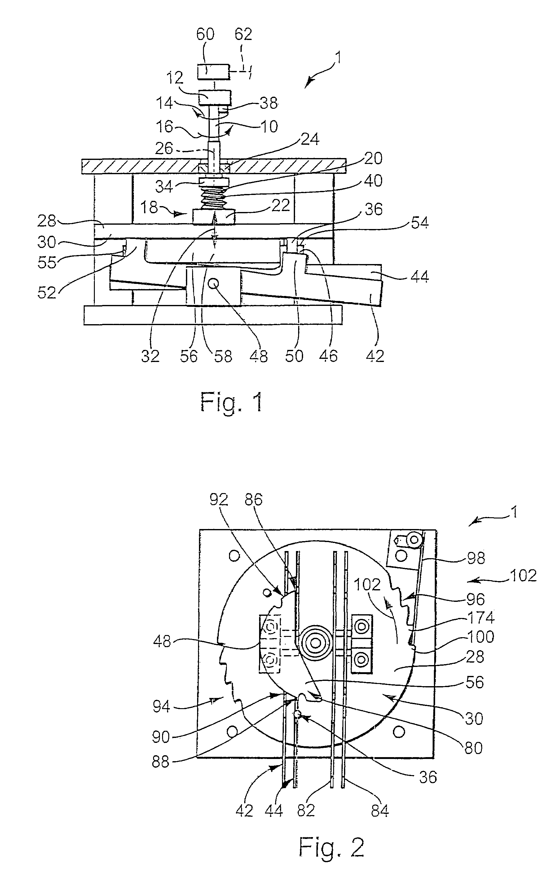
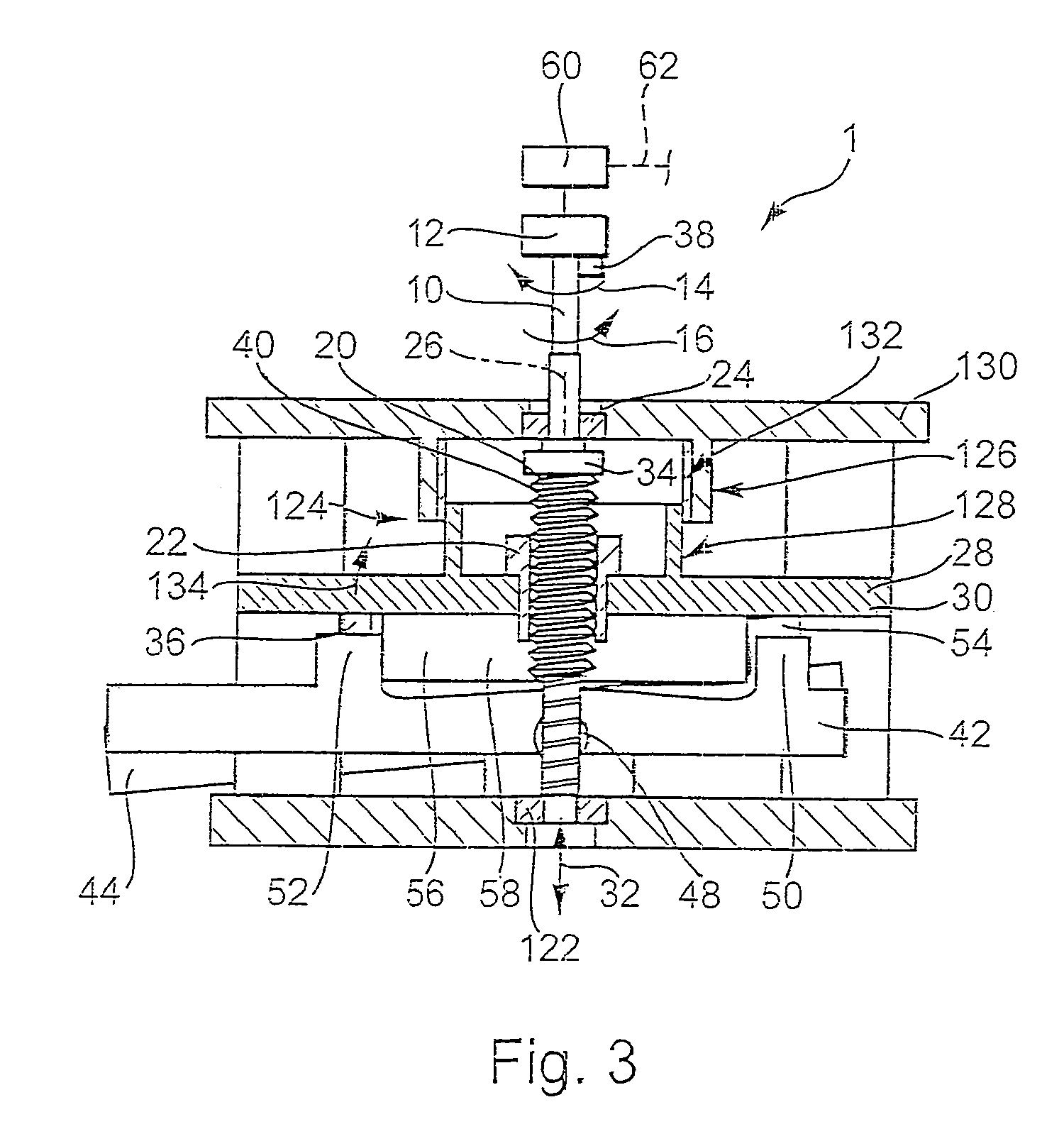
[0076]FIG. 1 shows an exemplary actuating apparatus 1 according to the invention in diagrammatic illustration.

[0077]The actuating apparatus 1 shown in FIG. 1 may for example be an actuating apparatus by means of which gears may be changed in a motor vehicle transmission or by which the changing of gears may be controlled.

[0078]Actuating apparatus 1 has a rotatably mounted drive shaft 10 that in this case is motor output shaft 10 of a drive device designed as an electric motor 12. This drive or output shaft 10 may alternatively be turned via the electric motor 12 about its longitudinal axis in a first direction, which is diagrammatically indicated by arrow 14, or in a second rotational direction, which is diagrammatically indicated by arrow 16 and is opposite the first rotational direction. Electric motor 12 may accordingly be designed to be switchable so that the drive shaft can be driven—as desired—in both directions.

[0079]Actuating apparatus 1 has a nut / threaded spindle assembly 1...


PUM


Abstract

The invention relates to an actuating apparatus that can be used, for example, as an actuating apparatus for a motor vehicle transmission, the select function and the shift function being guaranteed by this actuating apparatus and it being possible to effect this using exactly one electric motor, and it being possible, starting from an original gear, to alternatively engage at least three different target gears without it being necessary in between to shift into an intermediate gear.

Description

CROSS-REFERENCE TO RELATED APPLICATIONS[0001]This application is a divisional application claiming priority of U.S. patent application Ser. No. 10 / 710,963, filed Aug. 15, 2004, which has issued as U.S. Pat. No. 7,026,770, which application is incorporated herein by reference. U.S. patent application Ser. No. 10 / 710,963 claims priority of German Patent Application No. 10337625.9, filed Aug. 16, 2003, and German Patent Application No. 10359634.8, filed Dec. 18, 2003, which applications are incorporated herein by reference.BACKGROUND OF THE INVENTION[0002]The invention relates to an actuating apparatus, a use of such an actuating apparatus, a motor vehicle transmission having an actuating apparatus and a method for the automatic control of gear change processes and clutch actuations in a drive train of a motor vehicle. In a known actuating apparatus, by means of which gear change operations are controlled in an automated manner, two electric motors, each provided with an output shaft, ...

Claims


Application Information

Patent Timeline
Patent Type & Authority Patents(United States)
IPC IPC(8): B60K17/12F16H61/28F16H61/32
CPCF16H61/32F16H2061/2838F16H2061/2884F16H61/28
Inventor HEMPHILL, JEFFMCCONNELL, TREVORLINDEMANN, PATRICK
Owner SCHAEFFLER TECH AG & CO KG
Why Eureka
Try Eureka