System and method for sensing ambient light in an optical code reader

a technology of ambient light and code reader, applied in the field of optical code readers, can solve the problems of lack of aggressiveness, time-consuming and processing resources-consuming process of selecting settings,

Active Publication Date: 2007-12-04
SYMBOL TECH LLC
View PDF15 Cites 174 Cited by
  • Summary
  • Abstract
  • Description
  • Claims
  • Application Information

AI Technical Summary

Problems solved by technology

However, the process of selecting the settings is a time consuming and processing resources consuming process, including selecting arbitrary settings, imaging a target and determining if the settings need adjustment, making the adjustments and imaging the target with the adjusted settings.
The time delay incurred by the adjusting and setting process until a successful decode operation is performed may be perceived by the user as a lack of aggressiveness.

Method used


Image

  • System and method for sensing ambient light in an optical code reader
  • System and method for sensing ambient light in an optical code reader
  • System and method for sensing ambient light in an optical code reader

Examples


Embodiment Construction

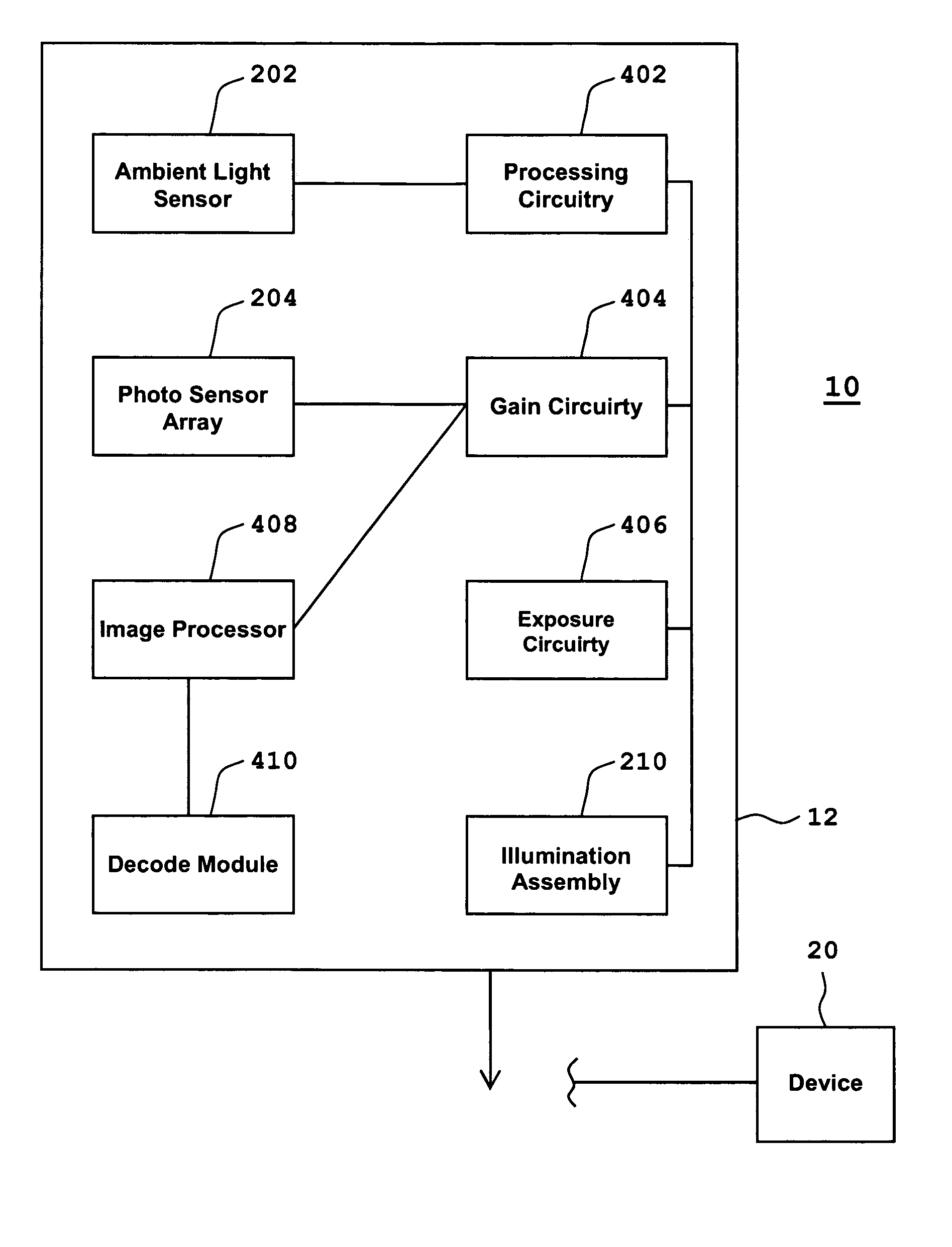
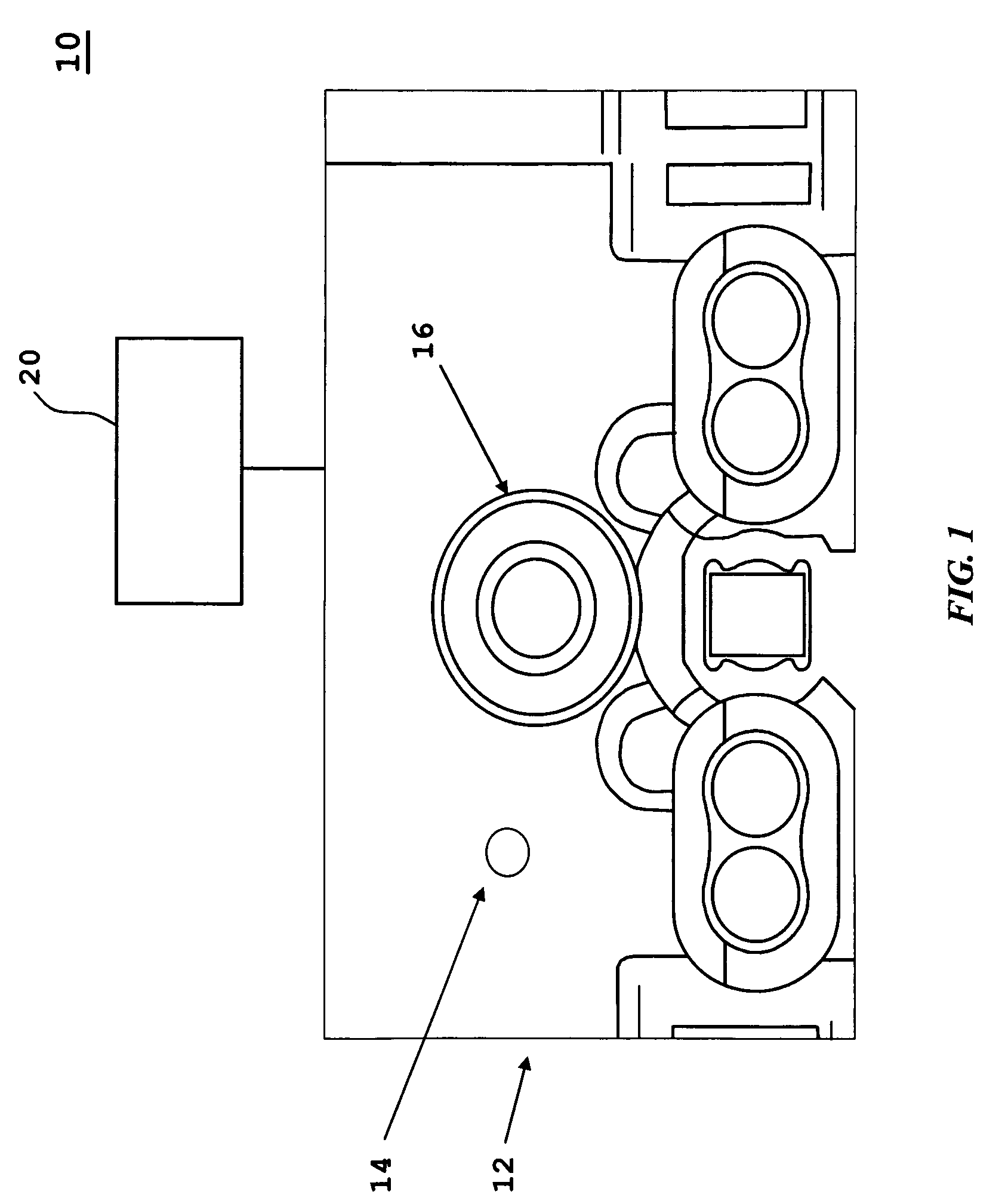
[0019]In FIG. 1 a front view of an exemplary optical code imaging system 10 is shown having a scanner 12 having first and second apertures 14, 16. The first aperture 14 is associated with an ambient light sensor (not shown) described below with respect to FIGS. 2-6. The second aperture 16 is associated with a photo sensor array (not shown), described below with respect to FIGS. 2-3. The scanner 12 may be in wired or wireless communication with at least one device 20, such as host terminal, other scanners, peripheral devices, etc.

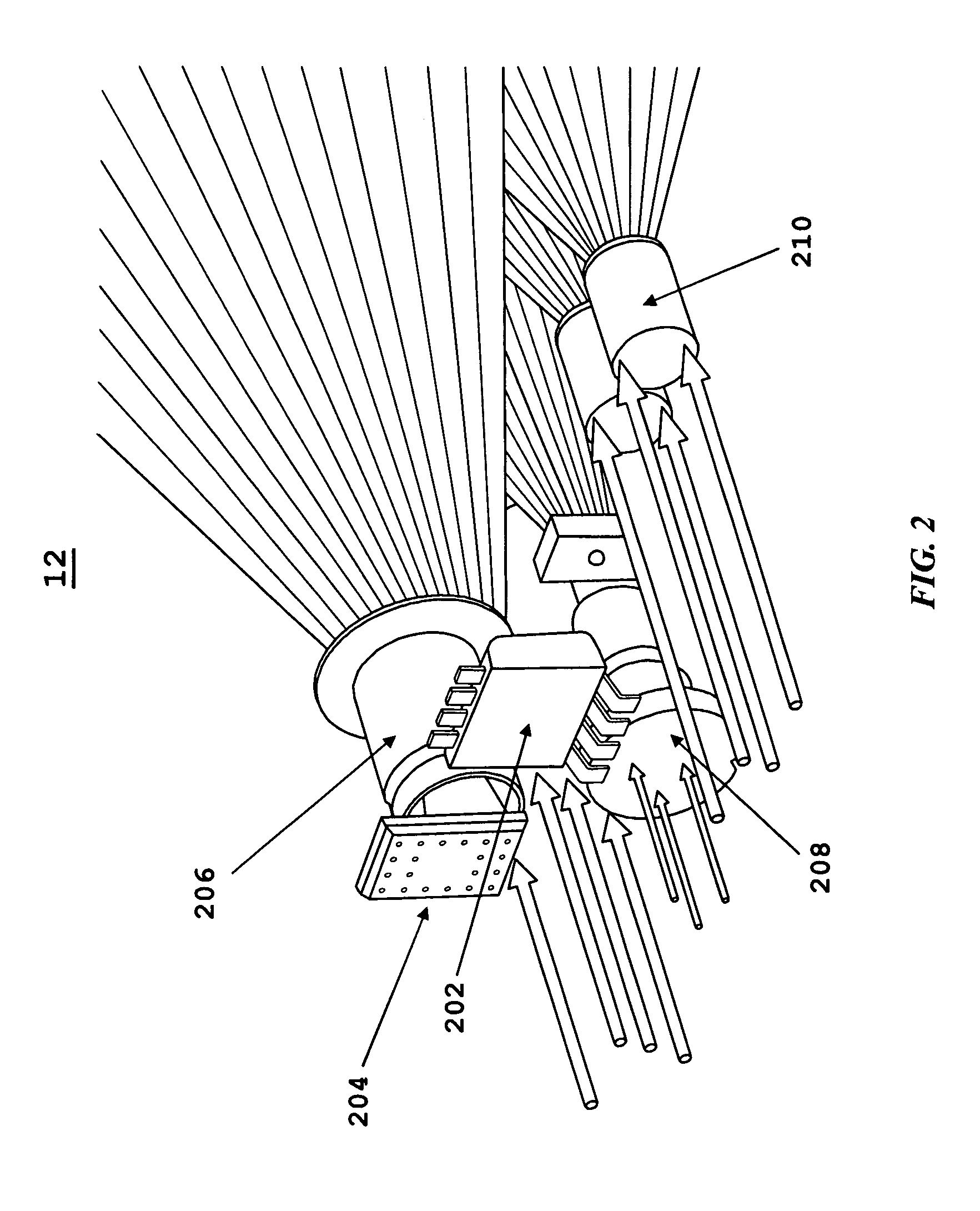
[0020]FIGS. 2 and 3 show respective back and exploded views of the scanner 12, where the scanner 12 is shown to further include an ambient light sensor 202, a photo sensor array 204, imaging optics 206, and optionally an aiming assembly 208 for providing assistance in aiming the scanner 12, and an illumination assembly 210 for providing illumination when performing an imaging operation.

[0021]The ambient light sensor 202 includes one or more photo sensors for...


PUM


Abstract

A system and method are provided for scanning an optical code, in which an optical code scanner system includes an ambient light sensor having at least one photo sensor for sensing ambient light conditions and generating at least one first electrical signal corresponding to the sensing of the ambient light conditions, and a photo sensor array having a plurality of photo sensors for sensing light reflected from the target being imaged and generating a plurality of second electrical signals corresponding the sensing of the reflected light. The optical code scanner system further includes at least one of exposure circuitry for controlling exposure during the sensing of the reflected light, gain circuitry for processing gain of at least a portion of the plurality of second electrical signals and an illumination assembly for providing illumination for illuminating the target; and a processing circuitry for processing at least a portion of the at least one first electrical signal and controlling at least one of the exposure circuitry, the gain circuitry and the illumination assembly in accordance with the processing of the at least a portion of the at least one first electrical signal.

Description

BACKGROUND OF THE INVENTION[0001]1. Field of the Invention[0002]This invention relates to optical code readers. In particular, this invention relates to a system and method for sensing ambient light in an optical code reader.[0003]2. Description of the Prior Art[0004]Optical code scanner systems have been developed heretofore for reading optical codes such as bar code symbols appearing on a label or on a surface of an article. The symbol itself is a coded pattern of indicia comprised of, for example, a series of bars of various widths spaced apart from one another to bound spaces of various widths, where the bars and spaces having different light reflecting characteristics. The scanners in scanning systems electro-optically transform the graphic indicia into electrical signals, which are decoded into alphanumeric characters that are intended to be descriptive of the article or some characteristic thereof. Such characters are typically represented in digital form and utilized as an i...

Claims


Application Information

Patent Timeline
Patent Type & Authority Patents(United States)
IPC IPC(8): G06K7/14G06K7/10
CPCG06K7/10752G06K7/10732
Inventor PATEL, MEHULCRAEN, PIERREBECKER, WILLIAM JOSHUABROWN, DANIEL
Owner SYMBOL TECH LLC
Why Eureka
Try Eureka