
Closed loop catheter coolant system

a closed loop catheter and coolant technology, applied in the field of coolant systems, can solve the problems of numerous problems or design constraints, failure modes of use, and difficulty in designing a safe and effective coolant circulation system, and still provide sufficient cooling capacity at a remote tip

Inactive Publication Date: 2007-12-04
MEDTRONIC CRYOCATH LP
View PDF26 Cites 66 Cited by
  • Summary
  • Abstract
  • Description
  • Claims
  • Application Information

AI Technical Summary

Benefits of technology

Ensures continuous coolant circulation, prevents leakage into the bloodstream, and allows for precise control of cooling power, enhancing the safety and effectiveness of cryoablation procedures while maintaining catheter flexibility.

Problems solved by technology

In general, when used for endovascular access to treat the cardiac wall, catheters of this type, in common with the corresponding earlier-developed radio frequency or electrothermal ablation catheter, must meet fairly demanding limitations regarding their size, flexibility, and the factors of strength, electrical conductivity and the like which affect their safety and may give rise to failure modes in use.
Furthermore, conditions of patient safety must be considered, raising numerous problems or design constraints for each particular system.
However, owing to the small size that such a catheter is required to assume for vascular insertion, or the awkwardness of handling a cryogenic treatment probe generally, the design of a safe and effective coolant circulation system which nonetheless dependably provides sufficient cooling capacity at a remote tip remains a difficult goal.
Among other common problems to be addressed while providing adequate thermal capacity, may be noted the leakage problem mentioned above, the problem of effectively preventing the catheter as a whole from being excessively cold or damaging tissue away from the intended site, and the problem of conduit or valve blockage owing for example to ice particles and the like.

Method used


Image

  • Closed loop catheter coolant system
  • Closed loop catheter coolant system
  • Closed loop catheter coolant system

Examples


Embodiment Construction

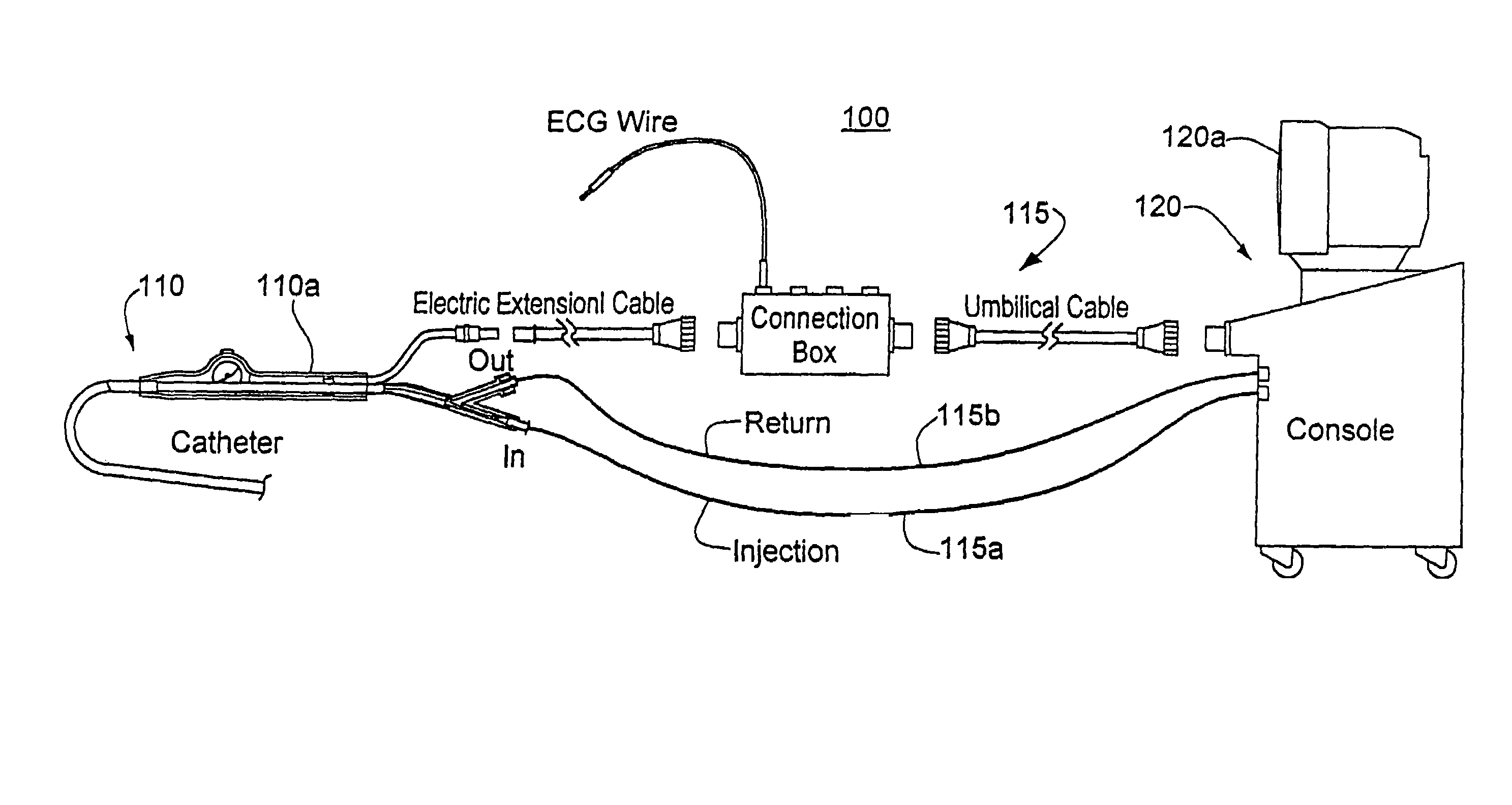
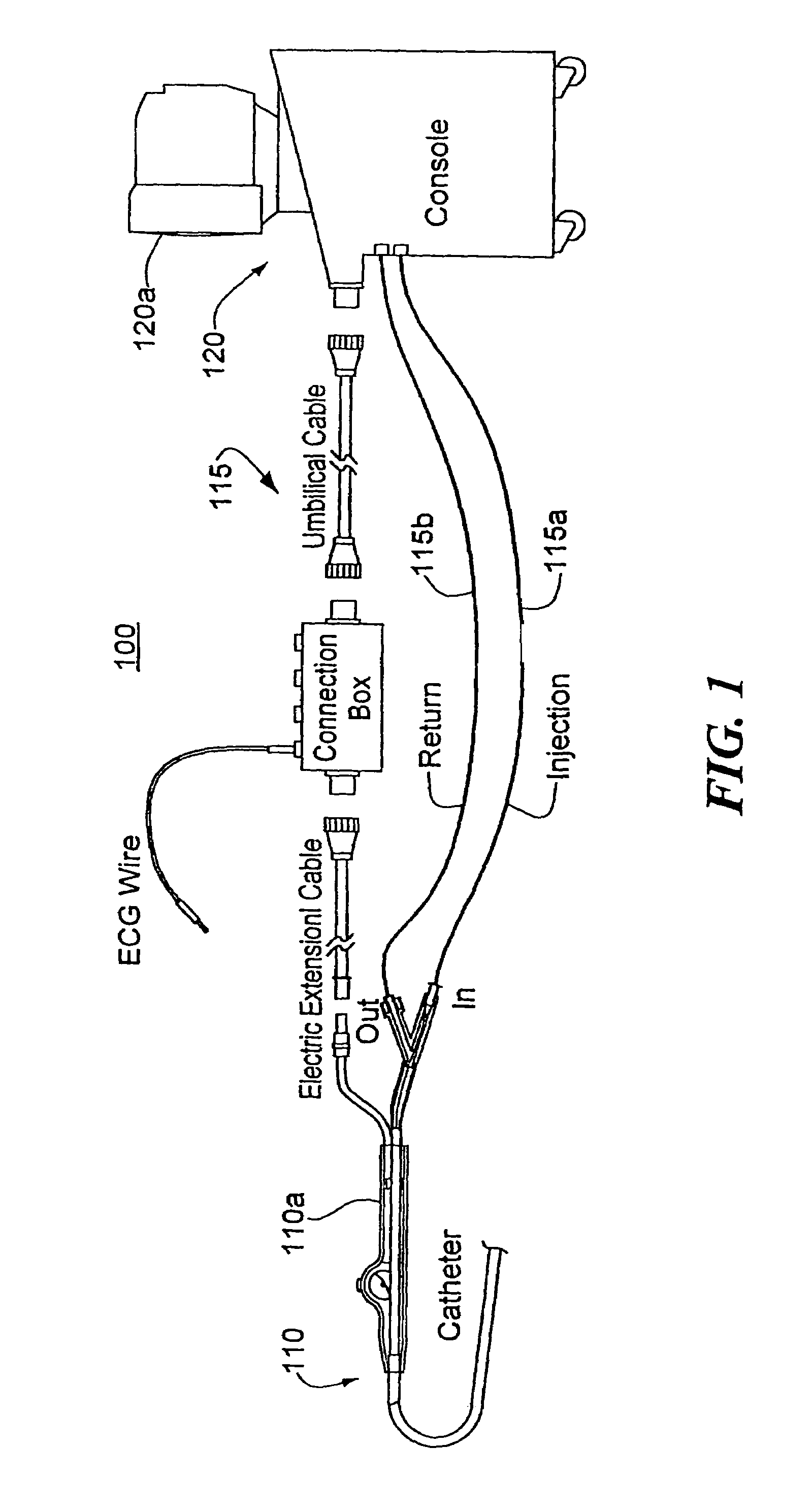
[0019]FIG. 1 shows a cryogenic treatment system 100 illustrating the general elements thereof. System 100 includes a treatment catheter 110 having a handle 110a, a treatment console 120 and number of connecting lines 115 which include signal lines for any cardiac monitoring or mapping functions as well as a coolant injection line 115a and a coolant return line 115b. As illustrated, the console includes a display screen 120a which may, for example, show both cardiac electrical signals and various status and control screens related to setting or reporting the cooling functions of the catheter or the ablation regimens being administered therewith.

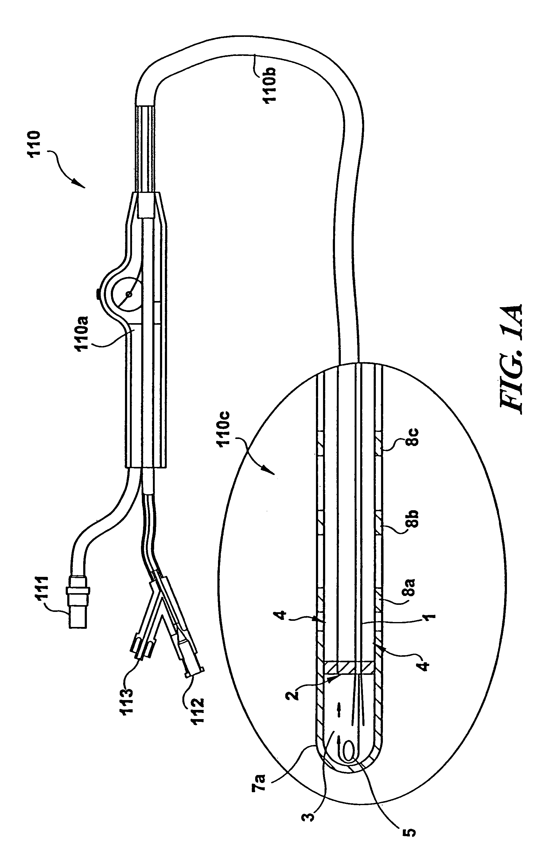
[0020]FIG. 1A shows in slightly greater detail a catheter 110 used in a system in accordance with the present invention. As shown, the handle 110a is equipped with input ports for an electrical connector 111, a coolant injection tube connector 112, and a return tube connector 113. These connect via various internal junctions or tubes passing t...


PUM


Abstract

A coolant system for a cryoablation or treatment probe such as a mapping or ablation catheter, or a treatment wand, includes a compressor and condenser having a low pressure inlet side and a high pressure outlet side, wherein the outlet side passes through a heat exchanger and is cooled by the inlet side and conditioned for injection to a catheter inlet. A vacuum return system connectable to the catheter outlet draws thermally expended coolant from the catheter and returns it to the low pressure inlet side. A motorized pressure regulator between the heat exchanger and the catheter inlet determines the pressure of coolant passing into the catheter and thus regulates the cooling rate for a selected mapping or ablation regimen. The low pressure compressor inlet supply preferentially conditions the pressurized coolant to ambient temperature or lower before injection into the catheter, allowing the coolant to travel through the body at ambient before expansion in the tip.

Description

CROSS-REFERENCE TO RELATED APPLICATIONS[0001]This application is a continuation of U.S. patent application Ser. No. 10 / 115,213, filed Apr. 01, 2002, by Jean-Pierre Lalonde, et al, entitled CLOSED LOOP CATHETER COOLANT SYSTEM, now U.S. Pat. No. 6,682,525, which application is a continuation of U.S. patent application Ser. No. 09 / 489,646, filed Jan. 24, 2000, by Jean-Pierre Lalonde, et al., entitled CLOSED LOOP CATHETER COOLANT SYSTEM, now issued U.S. Pat. No. 6,383,180 B1, which application is related to and claims priority from U.S. Provisional Application Ser. No. 60 / 117,175, filed Jan. 25, 1999, the entirety of all of which are incorporated herein by reference.STATEMENT REGARDING FEDERALLY SPONSORED RESEARCH[0002]Not Applicable.BACKGROUND OF THE INVENTION[0003]The present invention relates to a coolant system for a catheter or treatment wand used for cryotreatment of tissue. In particular, the coolant system is of the type which connects to a catheter and pumps coolant through the...

Claims


Application Information

Patent Timeline
Patent Type & Authority Patents(United States)
IPC IPC(8): A61B18/02A61B17/00A61B18/04A61B18/18A61F7/00
CPCA61B18/02A61B2017/00092A61F7/12A61B2018/0212A61B2018/0262A61B2017/00119
Inventor LALONDE, JEAN-PIERREABBOUD, MARWAN
Owner MEDTRONIC CRYOCATH LP
Learn More