Quantum cross-ambiguity function generator

a function generator and cross-ambiguity technology, applied in the field of calculating the cross-ambiguity function, can solve the problems of acousto-optical techniques, high computational intensity of caf, and relatively slow and expensive standard analog or digital systems

Inactive Publication Date: 2007-12-04
MDA INFORMATION SYST
View PDF42 Cites 18 Cited by
  • Summary
  • Abstract
  • Description
  • Claims
  • Application Information

AI Technical Summary

Problems solved by technology

The CAF is typically very computationally intensive to calculate, especially for broadband signals where a scale factor instead of, or in addition to, a frequency-shift term is used.
Accordingly, standard analog or digital systems are relatively slow and expensive except for the narrowband case.
Acousto-optical techniques have been proposed, but suffer from limited dynamic range and a very small TDOA search range.
These and other drawbacks exist with current systems.

Method used


Image

  • Quantum cross-ambiguity function generator
  • Quantum cross-ambiguity function generator
  • Quantum cross-ambiguity function generator

Examples


Embodiment Construction

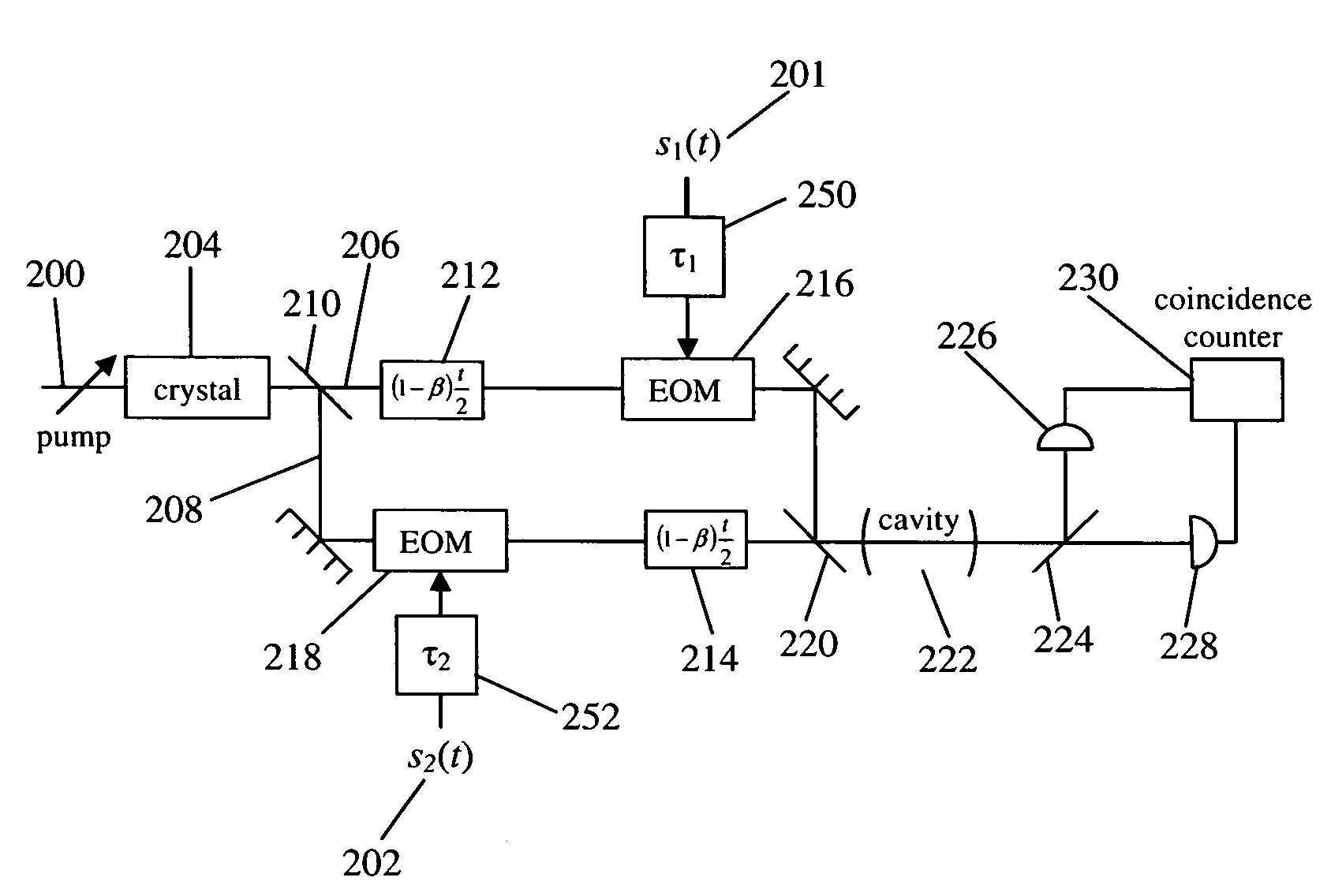
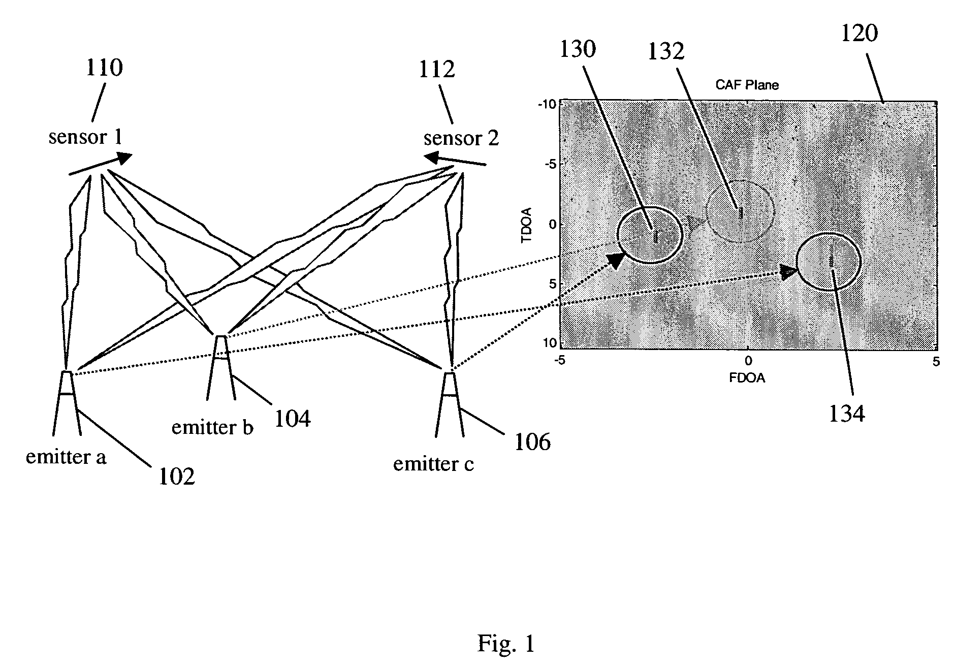
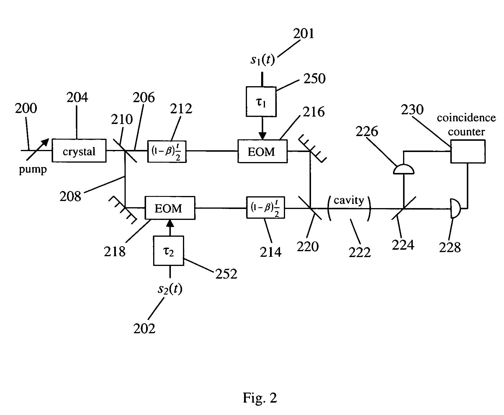
[0029]FIG. 1 is a schematic diagram depicting the use of the CAF to geolocate signal emitters 102, 104, 106. Two sensors 110, 112 at different locations and moving at different velocities are used to detect emitters 102, 104, 106. Sensors 110, 112 may be antennas, directional or otherwise. The signal from an emitter arrives at different times at sensors 110, 112, depending on their distance from the emitter. The signals arrive Doppler-shifted differently at sensors 110, 112 depending on the relative motion between each sensor and the emitter. The signals (or their representations) from sensors 110, 112 are brought together using techniques known in the art. The CAF is then used to scan CAF plane 120 by testing multiple time difference of arrival (TDOA) and frequency difference of arrival (FDOA) points in CAF plane 120 according to the embodiment of FIG. 1. TDOA and FDOA parameters that produce a locally maximum CAF value (e.g., 130, 132, 134) correspond to a signal emitter. The phys...


PUM


Abstract

A cross-ambiguity function generator (“CAF”) uses properties of quantum mechanics for computation purposes. The CAF has advantages over standard analog or digital CAF function generators, such as improved bandwidth. The CAF may be used for traditional geolocation or RADAR applications.

Description

RELATED APPLICATIONS [0001]The present application is related to U.S. Utility patent application Ser. No. 10 / 850,394 entitled “System and Method of Detecting Entangled Photons” to Kastella et al., which claims priority to U.S. Provisional Application Ser. No. 60 / 472,731 entitled “System and Method of Detecting Entangled Photons” to Kastella et al., the disclosures of which are expressly incorporated by reference herein in their entirety.FIELD OF THE INVENTION [0002]The present invention relates to systems for and methods of calculating the cross-ambiguity function (“CAF”) using quantum mechanical properties.BACKGROUND OF THE INVENTION [0003]The (narrow-band) CAF is generally given as[0004]CAF⁡(τ,δ)=∫0T⁢s1⁡(t)⁢s2*⁡(t-τ)⁢ⅇ-ⅈδ*t-τ)⁢ⅆt,where s1 and s2 each represent a signal reading, each of which may arise from a single emitted signal or be a composite of several component signals possibly originating from different signal emitters. The signal readings s1 and s2 may be radio frequency ...

Claims


Application Information

Patent Timeline
Patent Type & Authority Patents(United States)
IPC IPC(8): G01J9/00G01J1/42G01J1/58H04B10/30
CPCG01J1/42H04B10/30G01J1/58
Inventor ZAUGG, THOMAS C.
Owner MDA INFORMATION SYST
Why Eureka
Try Eureka