Distributed optic fiber vibrating sensor

A vibration sensor, distributed optical fiber technology, used in instruments, measuring devices, using wave/particle radiation, etc., to achieve the effects of high sensitivity, large monitoring area, and light weight

Active Publication Date: 2013-01-09
成都塔科光电技术有限公司 +1
View PDF5 Cites 28 Cited by
  • Summary
  • Abstract
  • Description
  • Claims
  • Application Information

AI Technical Summary

Problems solved by technology

Optical fiber interferometric distributed sensing can detect higher vibration frequency information, but there is a problem of low vibration spatial resolution

Method used


Image

  • Distributed optic fiber vibrating sensor
  • Distributed optic fiber vibrating sensor
  • Distributed optic fiber vibrating sensor

Examples


Embodiment Construction

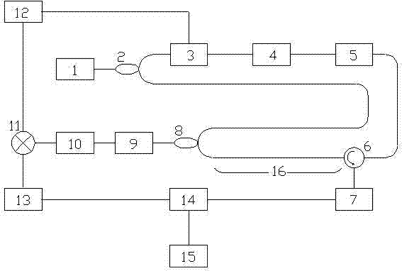
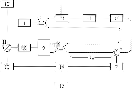
[0015] A kind of distributed optical fiber vibration sensor, its structure is: it is made up of light source 1, first coupler 2, acousto-optic modulator 3, erbium-doped fiber amplifier 4, optical filter 5, three-port circulator 6, first photoelectric detector Device 7, second coupler 8, second photodetector 9, high-pass filter 10, mixer 11, function generator 12, low-pass filter 13, data acquisition card 14, computer 15 and long-distance sensing fiber Composed of 16; the light source 1 is connected to the optical path of the input end of the first coupler 2, the first coupler 2 divides the input light into two paths, and one path of light is output to the acousto-optic modulator 3 as a detection signal (that is, the detection light hereinafter) , another path of light is output to the first input end of the second coupler 8 as a reference signal (that is, the reference light hereinafter); the acousto-optic modulator 3 modulates the input light and then outputs the light to the ...


PUM


Abstract

The invention discloses a distributed optic fiber vibrating sensor which consists of a light source, a first coupler, an acoustic optic modulator, an Erbium-doped optic fiber amplifier, an optic filter, a three-port circulator, a first photoelectric detector, a second coupler, a second photoelectric detector, a high-pass filter, a frequency mixer, a function generator, a low-pass filter, a data acquisition card, a computer and a long-distance sensing optic fiber. The distributed optic fiber vibrating sensor has the beneficial technological effects of detecting the vibrating positions and the vibrating frequencies at the same time and having relatively high resolution ratio for signals.

Description

Technical field [0001] The invention involves a fiber -fiber sensing technology, especially a distributed fiber vibration sensor. Background technique [0002] The amount of vibration measurement has potential use in the field of engineering, such as structural health monitoring, aerospace, petrochemical, power system and other safety monitoring.Traditional vibration measurement methods such as mechanical measurement method and electrical measurement method. There are problems with low sensitivity, large volume, and restrictions on the measurement of amplifying devices. The traditional vibration measurement method can only be measured.Therefore, the development of a high -performance vibration measurement system is imperative. [0003] Distributed optical fiber sensing technology refers to the continuous modulation of the optical waves in the fiber in a certain way along the external signal along the optical fiber transmission path to achieve real -time measurement of the contin...

Claims


Application Information

Patent Timeline
Patent Type & Authority Applications(China)
IPC IPC(8): G01H9/00
Inventor 朱涛
Owner 成都塔科光电技术有限公司
Why Eureka
Try Eureka