Color evaluation apparatus and method

a color evaluation and apparatus technology, applied in the field of color matching technique, can solve problems such as gaps in color appearance, and achieve the effect of improving color matching precision and high correlation with actual color appearan

Inactive Publication Date: 2006-01-17
CANON KK
View PDF36 Cites 27 Cited by
  • Summary
  • Abstract
  • Description
  • Claims
  • Application Information

AI Technical Summary

Benefits of technology

[0016]The present invention has been made to solve the aforementioned problems, and has as its object to calculate a precision evaluation value, which has high correlation with actual color appearance and is used to improve color matching precision independently of a change in condition such as a light source or the like.

Problems solved by technology

Hence, the evaluation results and color appearance have gaps.

Method used


Image

  • Color evaluation apparatus and method
  • Color evaluation apparatus and method
  • Color evaluation apparatus and method

Examples


first embodiment

(First Embodiment)

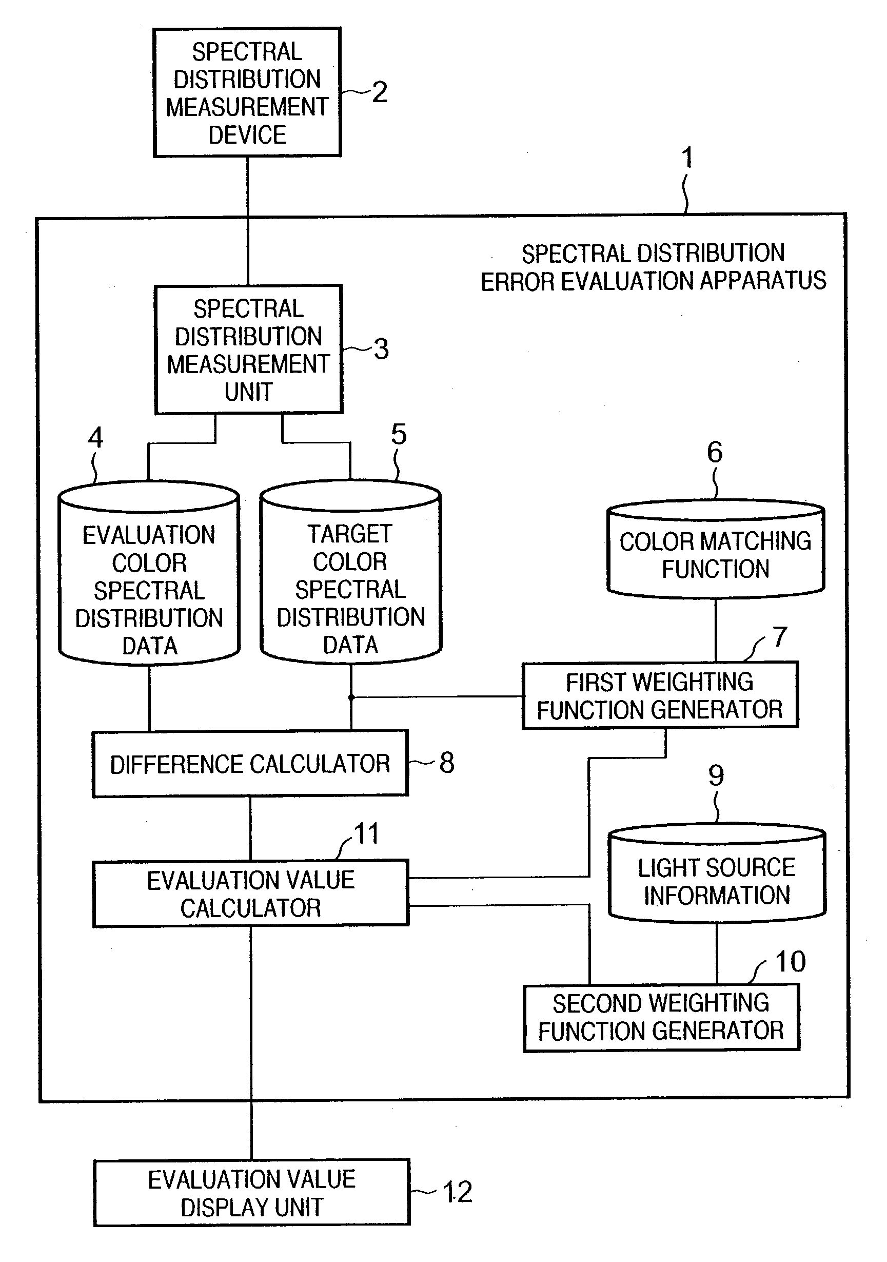
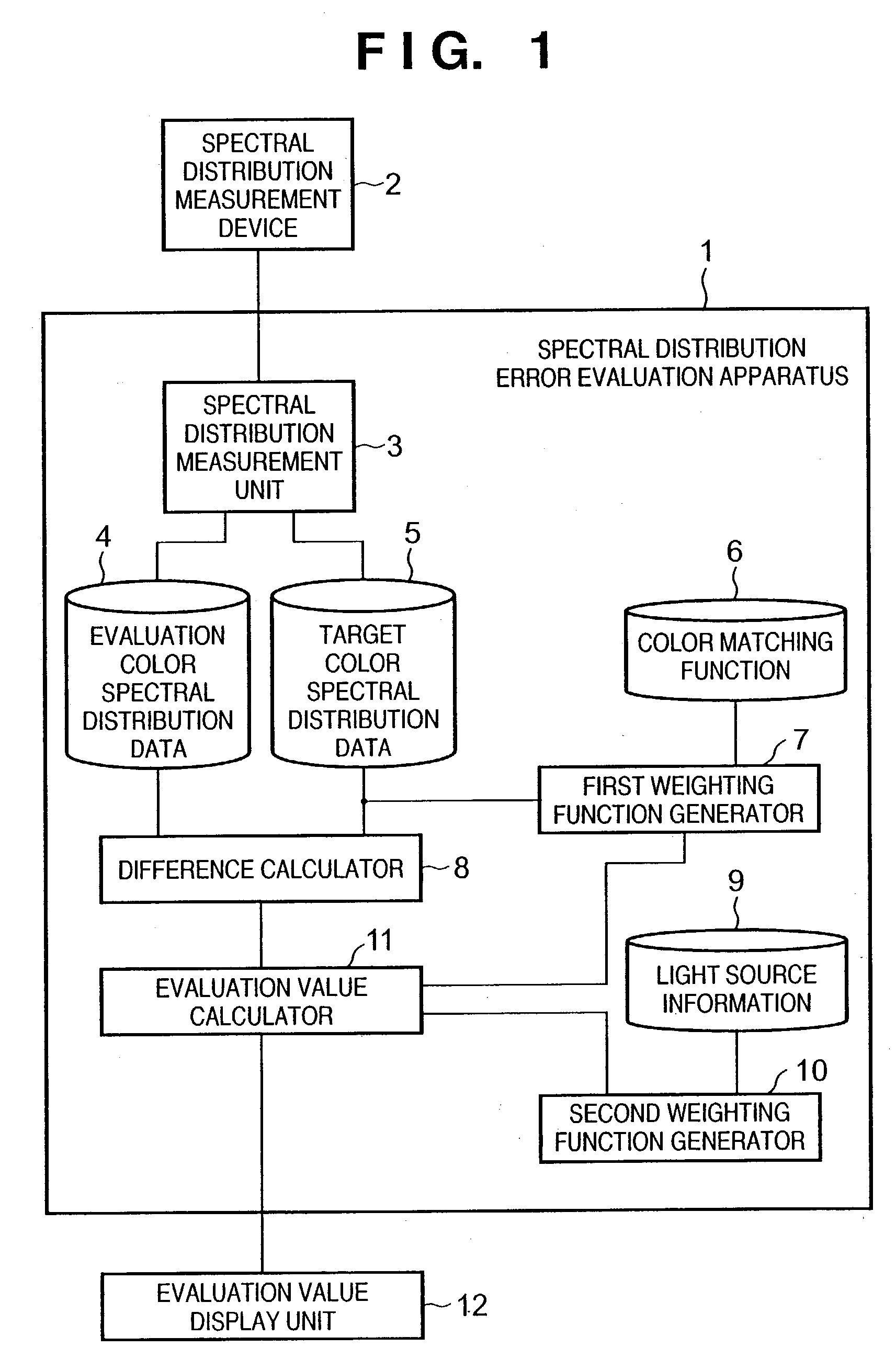
[0044]FIG. 1 is a block diagram showing the arrangement of a spectral distribution error evaluation apparatus according to the first embodiment. Referring to FIG. 1, reference numeral 1 denotes a spectral distribution error evaluation apparatus of this embodiment.

[0045]Reference numeral 2 denotes a spectral distribution measurement device, which measures the spectral distribution of an object. The spectral distribution measurement device comprises, e.g., a spectrophotometer. Reference numeral 3 denotes a spectral distribution measurement unit, which controls the spectral distribution measurement device 2. Reference numeral 4 denotes an evaluation color spectral distribution data storage unit, which stores the spectral distribution of an object to be evaluated (evaluation color spectral distribution) output from the spectral distribution measurement unit 3. Reference numeral 5 denotes a target color spectral distribution data storage unit, which stores the spectral ...

second embodiment

(Second Embodiment)

[0066]The second embodiment of the present invention will be described in detail below with reference to the accompanying drawings. FIG. 9 is a block diagram showing the arrangement of an image processing apparatus according to the second embodiment of the present invention. Reference numeral 901 denotes a spectral distribution error evaluation apparatus according to the second embodiment.

[0067]Reference numerals 902 and 903 denote devices, each of which comprises a spectrophotometer or the like, and is used to measure the spectral distribution of an object. Reference numerals 904 and 905 denote spectral distribution measurement units, which respectively control the spectral distribution measurement devices 902 and 903. Reference numeral 906 denotes an evaluation color spectral distribution data storage unit, which stores spectral distribution data output from the spectral distribution measurement unit 904. Reference numeral 907 denotes a target color spectral dis...


PUM

PropertyMeasurementUnit
visible wavelength rangeaaaaaaaaaa
color evaluationaaaaaaaaaa

Abstract

A spectral distribution error evaluation apparatus is used to evaluate precision of color matching between evaluation and target colors. A first weighting function generator generates a first weighting function on the basis of color matching functions, wavelength characteristics which are independent of a light source of the target color, and visual characteristics which depend on wavelengths. A second weighting function generator generates a second weighting function on the basis of light source information of selected light sources. A difference calculator calculates error values between the evaluation and target colors for respective frequencies. An evaluation value calculator applies the first and second weighting functions to the error values, and calculates the sum total of the error values as an evaluation value. In this way, a precision evaluation value which has high correlation with actual color appearance and is used to improve the color matching precision can be calculated independently of a change in condition such as a light source or the like.

Description

FIELD OF THE INVENTION[0001]The present invention relates to a color matching technique and, more particularly, to a technique for evaluating an error between an original color and reproduction color upon spectrally reproducing a color.BACKGROUND OF THE INVENTION[0002]Upon reproducing colors by a display, printer, and the like, color matching is normally made by a method of matching the tristimulus values of an original with those of an output on the basis of the trichromatic theory. A human being converts the spectral reflectance of an object as a continuous function in a visible wavelength range (about 380 to 780 nm) into responses (to be referred to as tristimulus values hereinafter) of three different cells called cones, which are distributed on the retina, and perceives colors of the object on the basis of the tristimulus values. As typical calorimetric systems used to quantify the tristimulus values, an XYZ calorimetric system and CIELAB calorimetric system are known. The XYZ ...

Claims


Application Information

Patent Timeline
Patent Type & Authority Patents(United States)
IPC IPC(8): G01N21/25G01J3/46G06T1/00H04N1/46H04N1/60
CPCG01J3/46G01J3/465G01J3/463G01J3/462
Inventor TAKAHASHI, KOSEIYAMADA, OSAMU
Owner CANON KK
Why Eureka
Try Eureka