Material analysis

a technology of thermography and material analysis, applied in the field of material analysis, can solve the problems of poor signal-to-noise ratio, system does not allow thermal lag, and takes an appreciable amount of time for heat pulses

Inactive Publication Date: 2006-03-28
AIRBUS UK
View PDF52 Cites 30 Cited by
  • Summary
  • Abstract
  • Description
  • Claims
  • Application Information

AI Technical Summary

Benefits of technology

[0012]delay means for introducing a variable delay between said emission of each one of said series of

Problems solved by technology

As the thermal images produced by the camera are captured at the same moment as when the halogen lamp is switched on, the system does not allow for thermal lag.
Our studies have shown that it takes an appreciable amount of time for the heat pulses produced by the lamp to be transmitted from the surface of the sample facing the lamp through the thickness of the sample to the sample surface facing the camera.
As a result of this, the camera is unabl

Method used


Image

  • Material analysis
  • Material analysis
  • Material analysis

Examples


Embodiment Construction

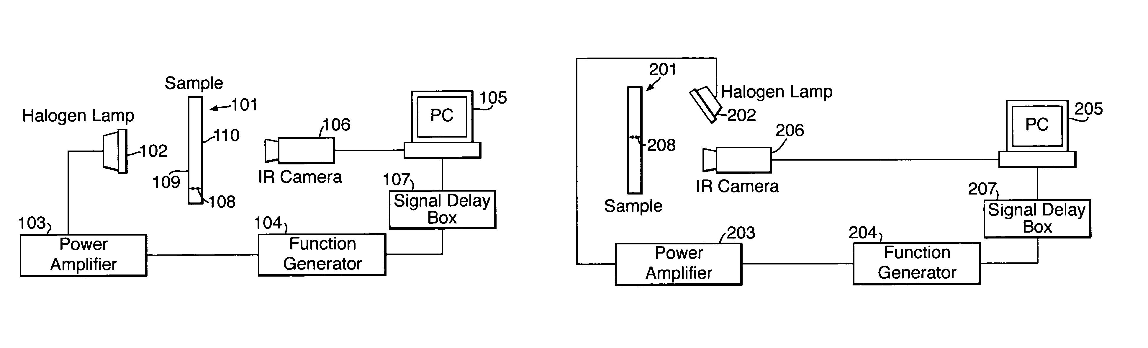
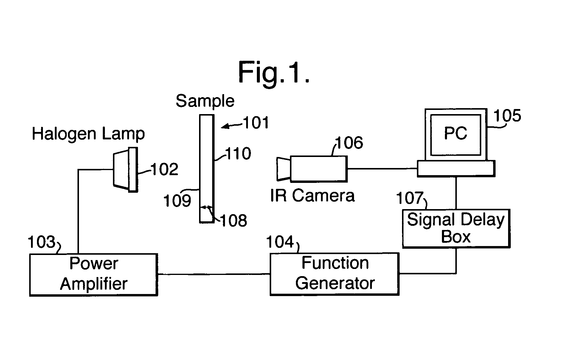
[0029]In FIG. 1, a sample 101 of the material to be analysed is positioned with one surface 109 facing a halogen lamp 102. An opposite surface 110 of the sample 101 faces an infra-red camera 106. The thickness of the sample 101 between the two opposite surfaces 109 and 110 is indicated by arrows 108. Although in the example of FIG. 1 the thickness 108 of the sample material 101 is less than the length of the sample, in this specification the term “thickness” is intended to mean a distance between any two generally opposed surfaces of a material which is to be analysed.

[0030]The halogen lamp 102 is connected to a power amplifier 103 driven by a function generator 104 which in use switches the halogen lamp 102 on and off at a predetermined frequency provided by the sinusoidal function gen rator 104. The lamp 102 emits heat pulses in a direction mainly towards the surface 109 of the sample 101 adjacent to the lamp.

[0031]The function generator 104 is also connected via a signal delay bo...


PUM


Abstract

In thermography apparatus, a lamp 102 is modulated sinusoidally and a camera 106 captures thermal images at the modulated frequency, but delayed by an adjustable preset delay. A signal delay box 107 is connected between a sinusoidal modulation signal function generator 104 and the camera 106. The delay box introduces a delay to the function generator signal so that the thermal image is captured after a period of time, resulting in an enhanced image.

Description

[0001]This application is the US national phase of international application PCT / GB00 / 03938 filed 13 Oct. 2000, which designated the US.BACKGROUND OF THE INVENTION[0002]1. Field of the Invention[0003]The present invention relates to material analysis, and more particularly to material analysis using thermography.[0004]2. Discussion of Prior Art[0005]In known lock-in thermography material analysis a sample of a material to be analysed is positioned between a halogen lamp and an infra-red camera. The lamp is switched on and off by a sinusoidally modulated signal so that heat pulses are emitted towards the sample at a particular frequency, generating sinusoidal thermal waves inside the material. Reflections produced by defects and interfaces (normally boundaries between different materials) in the sample interfere with incoming waves transmitted by the lamp to produce a wave pattern at the surface of the material. The infra-red camera captures a thermal image of the wave pattern at the...

Claims


Application Information

Patent Timeline
IPC IPC(8): G01J5/02G01N25/72
CPCG01N25/72
Inventor BATES, DANIEL
Owner AIRBUS UK
Why Eureka
Try Eureka