Maximizing power generation in and distributing force amongst piezoelectric generators

a technology of piezoelectric generators and generators, applied in piezoelectric/electrostrictive/magnetostrictive devices, generators/motors, apparel, etc., can solve problems such as the breakage of piezoelectric elements

Active Publication Date: 2007-12-04
MULLEN JEFFREY D
View PDF21 Cites 30 Cited by
  • Summary
  • Abstract
  • Description
  • Claims
  • Application Information

AI Technical Summary

Benefits of technology

[0007]It is an object of the present invention to array and utilize piezoelectric / piezoelectric generators as power supplies (e.g., voltage sources). It is also an object of the present invention to integrate properly configured piezoelectric generators into applications that can recapture expelled kinetic, or other, energy—energy that would otherwise be wasted.
[0010]A guide-frame may be aligned with a piezoelectric element. Such a guide-frame may be constructed such that the piezoelectric element touches the guide-frame when the piezoelectric element is displaced by its maximum displacement. Without such a guide-frame, a piezoelectric element may break if the strain is too great for the piezoelectric element to handle. In providing a guide-frame, the piezoceramic is stopped from being displaced more than its maximum displacement. Thus, a piezoelectric element can be downsized so the piezoelectric elements generates its maximum potential (e.g., is physically distorted by its maximum displacement) more frequently without breaking.
[0014]Springs may also be aligned with piezoelectric generators, or arrays, in order to increase the number of times that those piezoelectric elements are strained for each strain-providing force. For example, springs may be included in a piezoelectric array that is placed in a shoe. Thus, a piezoelectric array may be strained more than once (e.g., twice) each time a heal strike occurs.

Problems solved by technology

Without such a guide-frame, a piezoelectric element may break if the strain is too great for the piezoelectric element to handle.

Method used


Image

  • Maximizing power generation in and distributing force amongst piezoelectric generators
  • Maximizing power generation in and distributing force amongst piezoelectric generators
  • Maximizing power generation in and distributing force amongst piezoelectric generators

Examples


Embodiment Construction

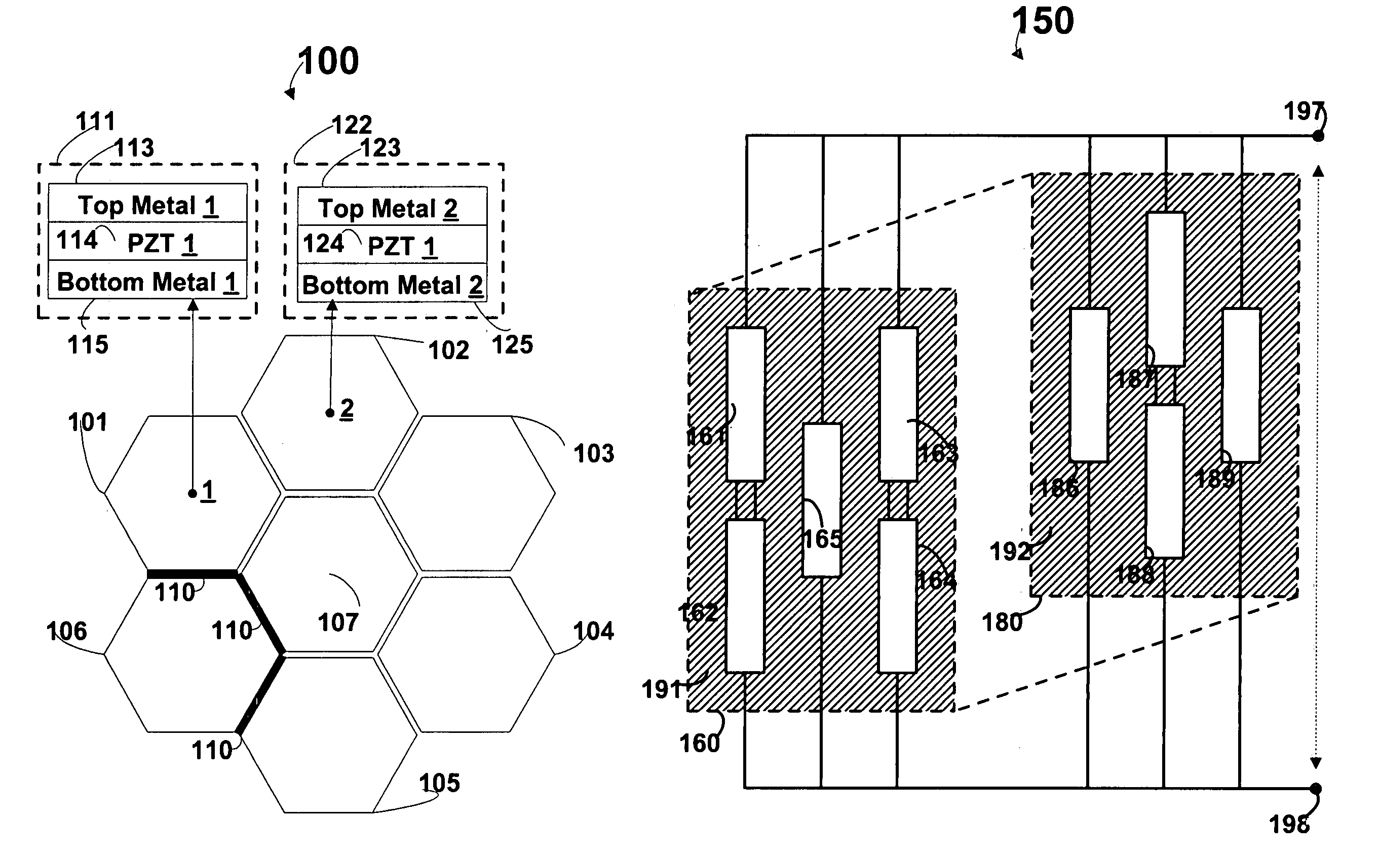
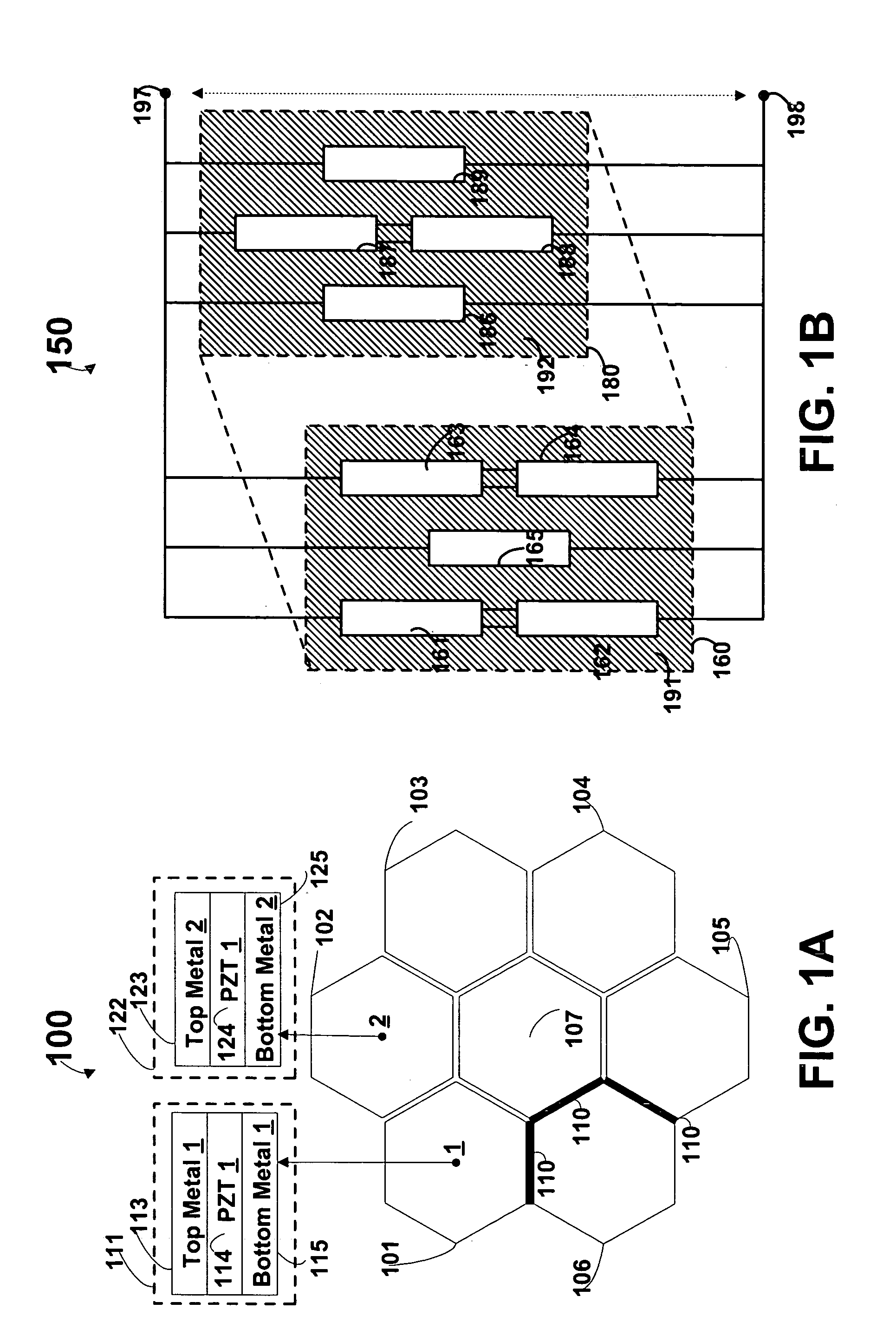
[0029]FIG. 1A shows piezo array 100 that includes a honeycomb of piezo generators 101–107. An isolation layer may be included between each of piezo generators 101–107 such that the generators are electrically isolated from each other. For example, isolation layer 110 electrically isolates piezo generator 106 from piezo generator 105. Piezo generators 101–107 may be any shape. For example, piezo generators 101–107 may be piezoelectric rectangles, squares, discs, hemispheres, stacks, and tubes.

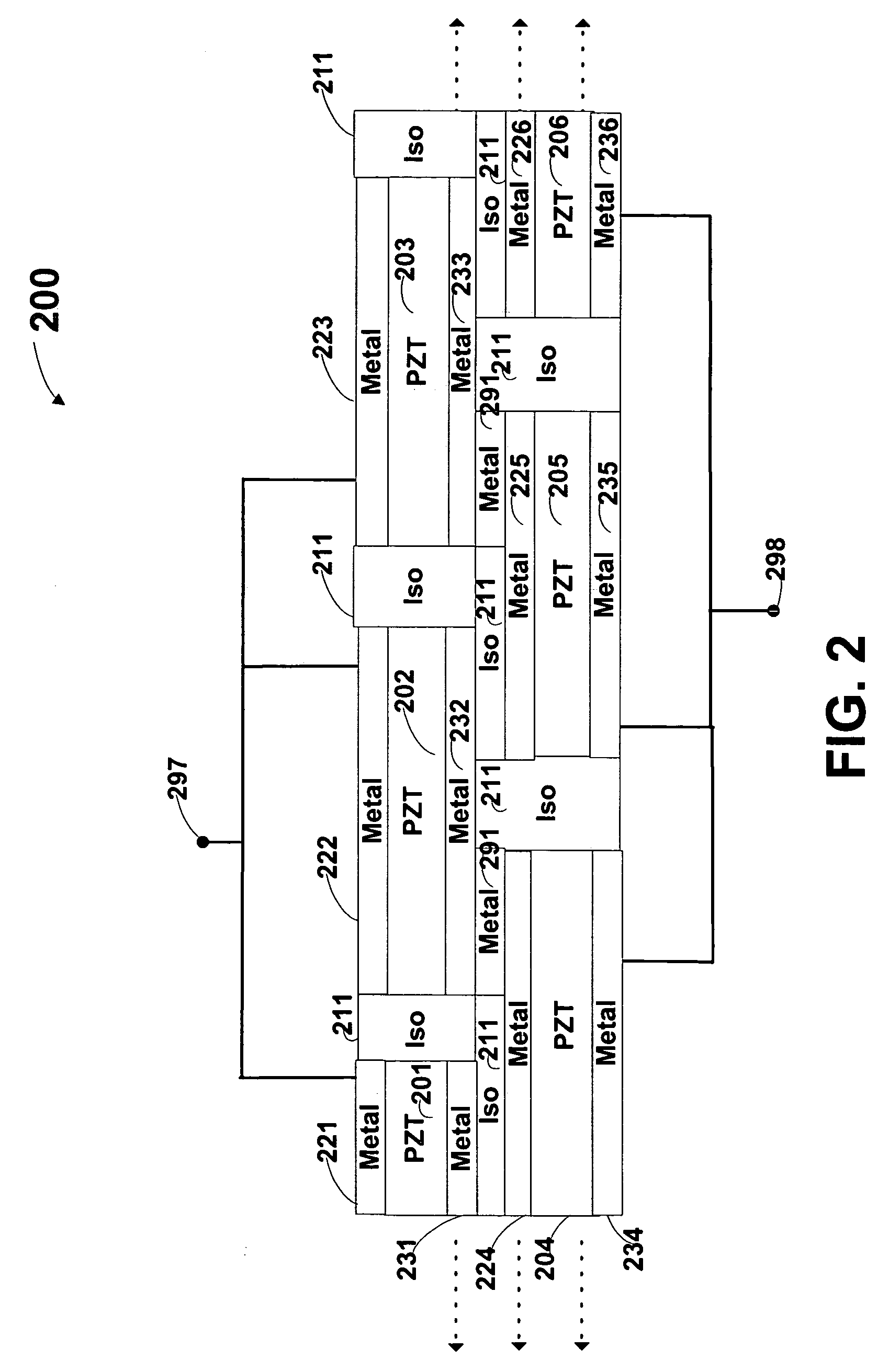
[0030]Piezo generators 101 and 102 may take the form of configurations 111 and 122, respectively. Configurations 111 and 122 include a piezoceramic element sandwiched between two layers of metal. Preferably, the metal is flexible and merely acts as a conductive coating to the piezoceramic. In this manner, the metal layers are preferably thin when compared to the thickness of the piezoceramic element.

[0031]Although piezo generators 101–107 are isolated as a result of isolation 110, piezo generato...


PUM


Abstract

It is an object of the present invention to array and utilize piezoelectric generators. It is also an object of the invention to implement properly configured piezoelectric generators into applications that can recapture expelled kinetic energy that is otherwise wasted. Particularly, piezoelectric generators, or arrays, may be, for example, placed in shoes, clothing, tires, roads, and sidewalks in order to recapture the energy expelled in everyday human activities (e.g., walking, moving, and driving).

Description

CROSS-REFERENCE TO RELATED APPLICATION[0001]This application claims the benefit of U.S. Provisional Patent Application No. 60 / 449,371, filed Feb. 21, 2003, which is hereby incorporated by reference in its entirety.BACKGROUND OF THE INVENTION[0002]This invention relates to piezoceramics and more particularly to piezoelectric generators. More particularly, this invention relates to beneficial applications that can be realized with properly arrayed and configured piezoelectric generators.[0003]Piezoelectrics have two general configurations. First, a piezoelectric actuator may be constructed. Here, the piezoelectric element is physically distorted when an electric potential is placed across the piezoelectric actuator. A piezoelectric actuator may be configured to bend or stretch / compress as a result of an electric potential. Second, a piezoelectric generator may be constructed. Here, the piezoelectric element generates an electric potential when physically distorted (e.g., strained). A ...

Claims


Application Information

Patent Timeline
Patent Type & Authority Patents(United States)
IPC IPC(8): H01L41/08A43B3/00H01L41/113
CPCA43B3/00A43B3/0005H02N2/18H01L41/113A43B3/0015A43B3/38A43B3/34H10N30/30H10N30/308
Inventor MULLEN, JEFFREY D
Owner MULLEN JEFFREY D
Why Eureka
Try Eureka