Methods and systems for rate-based flow control between a sender and a receiver

a flow control and sender technology, applied in the field of method and system for flow control between a sender and a receiver, can solve the problem that sending per packet acknowledgement consumes bandwidth on the path between the receiver, and achieve the effect of smoother perception of rate fluctuations at the application

Inactive Publication Date: 2007-12-04
NORTH CAROLINA STATE UNIV
View PDF4 Cites 177 Cited by
  • Summary
  • Abstract
  • Description
  • Claims
  • Application Information

AI Technical Summary

Benefits of technology

[0014]TEAR can determine the “appropriate” receiving rates of receivers based on congestion signals observed at the receiver, such as packet arrivals, packet losses, and timeouts. Using these signals, TEAR emulates the TCP sender's flow control functions at receivers, including slow start, fast recovery, and congestion avoidance. This emulation allows receivers to estimate a TCP-friendly rate for the congestion conditions observed in their forward paths. Further, TEAR smoothes estimated values of steady-state TCP throughput by filtering noise. This smoothed rate estimate will be reflected in the rate adjustment of receiving rates (e.g., by asking the sender to set the transmission rate to the smoothed rate estimate). Therefore, TEAR-based flow control can adjust receiving rates to a TCP-friendly rate without actually modulating the rates to probe for spare bandwidth or to react to packet losses directly. Thus, the perceived rate fluctuations at the application are much smoother than in TCP and more suitable for streaming media applications.

Problems solved by technology

As discussed above, sending per packet acknowledgements consumes bandwidth on the path between the receiver and the sender.

Method used


Image

  • Methods and systems for rate-based flow control between a sender and a receiver
  • Methods and systems for rate-based flow control between a sender and a receiver
  • Methods and systems for rate-based flow control between a sender and a receiver

Examples


Embodiment Construction

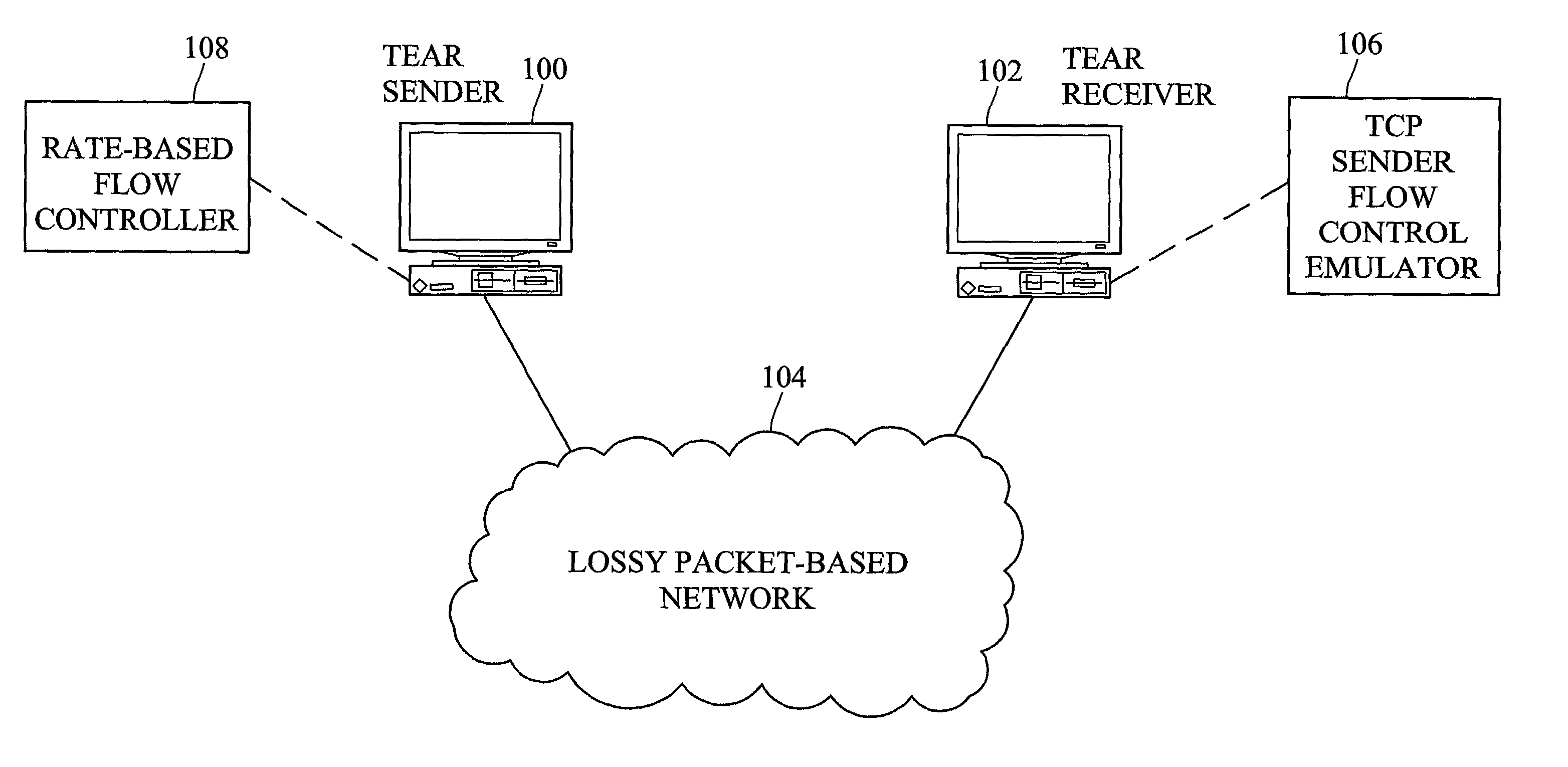
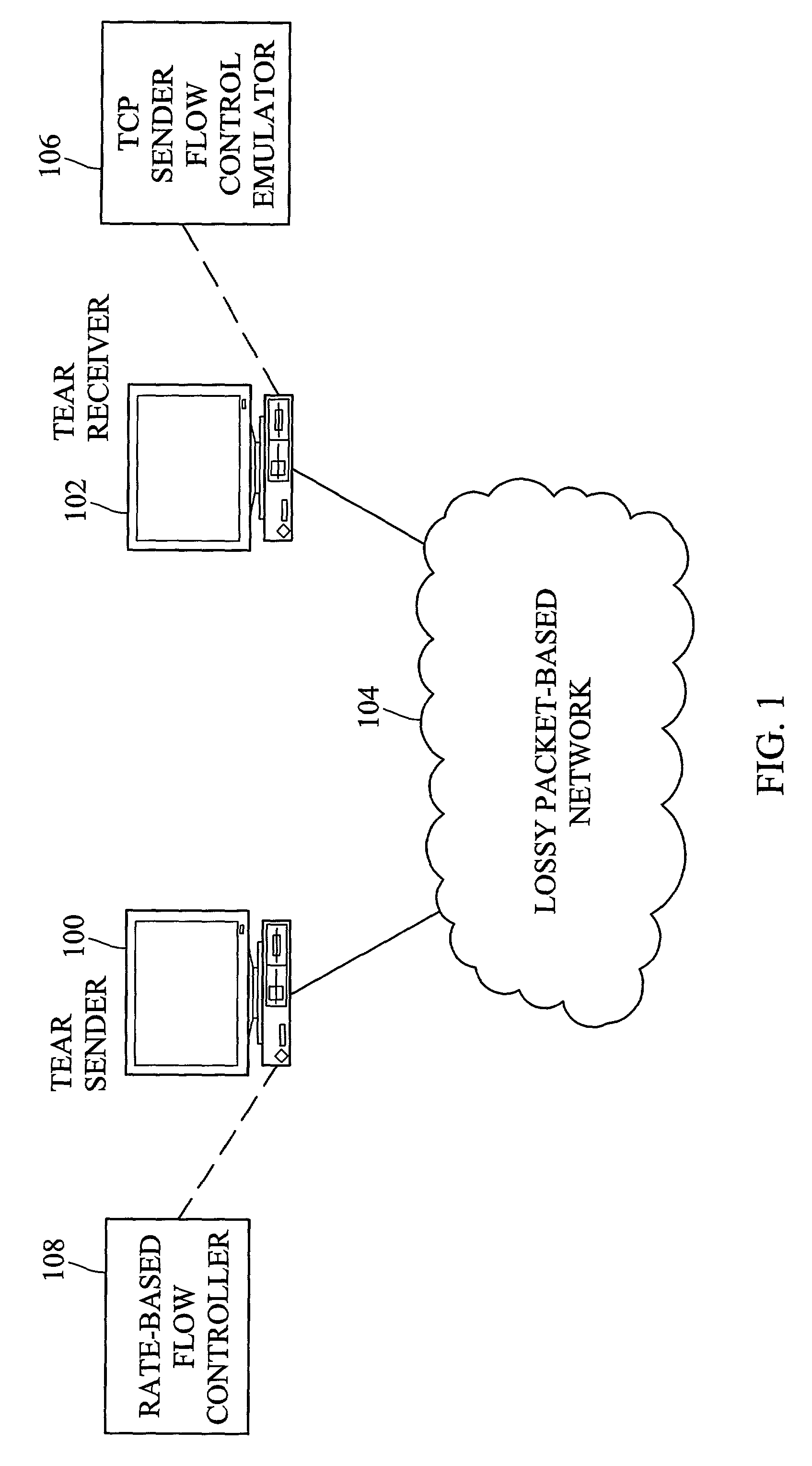
[0055]FIG. 1 illustrates a TEAR sender and a TEAR receiver including a rate-based flow control system according to an embodiment of the present invention. In FIG. 1, TEAR sender 100 and TEAR receiver 102 communicate over a lossy packet-based network 104, such as the Internet. TEAR sender 100 and tear receiver 102 may include general-purpose computing platforms, such as personal computers or workstations. According to an important aspect of the invention, TEAR receiver 102 includes a TCP sender flow control emulator 106 for emulating the flow control functions normally performed by a TCP sender and forwarding rate information to TEAR sender 100. TEAR sender 100 includes a rate-based flow controller 108 for controlling the flow of packets to TEAR receiver 102 based on rate information received from TEAR receiver 102.

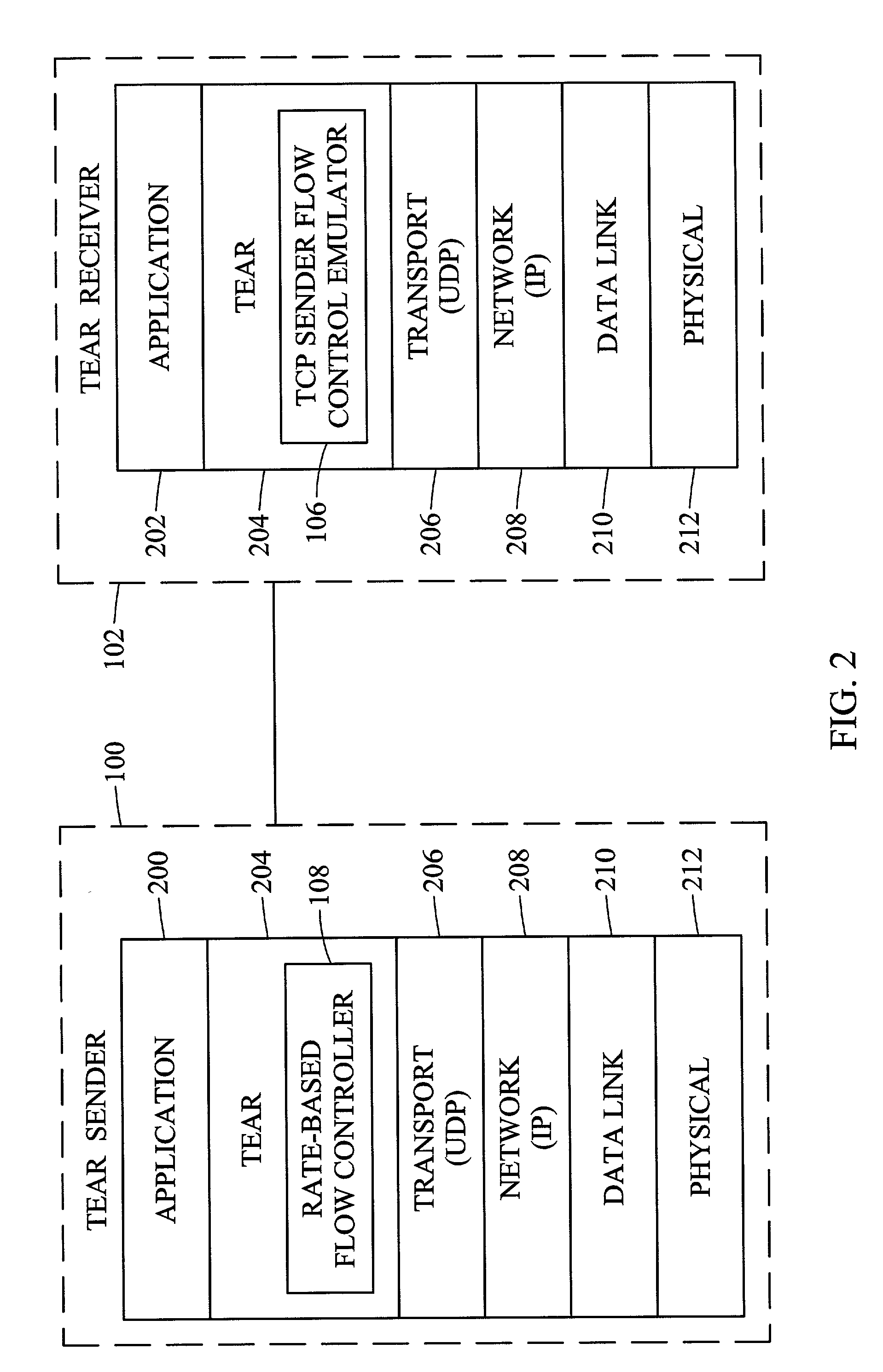
[0056]FIG. 2 is a protocol layer diagram illustrating TEAR sender 100 and TEAR receiver 102 in more detail. In FIG. 2, TEAR sender 100 and TEAR receiver 102 each include c...


PUM


Abstract

Methods and systems for rate-based flow control between a sender and a receiver are disclosed. A receiver performs TCP-like flow control calculations based on packets received from a sender. The receiver calculates a transmission rate and forwards the transmission rate to the sender. The sender sends packets to the receiver at the rate calculated by the receiver. Thus, rather than having sender-based flow control as in TCP, the receiver controls the rate at which packets are delivered.

Description

PRIORITY CLAIM[0001]This application claims the benefit of U.S. provisional patent application No. 60 / 252,153 filed Nov. 21, 2000, the disclosure of which is incorporated herein by reference in its entirety.TECHNICAL FIELD[0002]The present invention relates to methods and systems for flow control between a sender and a receiver in a computer network. More particularly, the present invention relates to methods and systems for rate-based flow control between a sender and a receiver.BACKGROUND ART[0003]As the Internet becomes diversified in its capabilities, it becomes feasible to offer services that were not possible under earlier generations of Internet technologies. Real-time multimedia streaming and IP multicast are two such emerging technologies. The development and use of commercial applications based on these technologies, such as Internet telephony, will become increasingly prevalent, and their traffic will constitute a large portion of the Internet traffic in the future.[0004]...

Claims


Application Information

Patent Timeline
Patent Type & Authority Patents(United States)
IPC IPC(8): H04J1/16H04L12/56H04L29/06
CPCH04L29/06H04L47/10H04L47/11H04L69/163H04L47/283H04L47/37H04L47/193H04L69/16H04L9/40
Inventor RHEE, INJONG
Owner NORTH CAROLINA STATE UNIV
Why Eureka
Try Eureka