Utility based filtering mechanism for PMTU probing

a filtering mechanism and utility-based technology, applied in the field of network communication, can solve problems such as congestion, inability to timely or adequate, and inability to respond to and throughput, and achieve the effect of reducing the number of users, and improving the quality of servi

Active Publication Date: 2007-12-04
MICRO FOCUS SOFTWARE INC
View PDF11 Cites 43 Cited by
  • Summary
  • Abstract
  • Description
  • Claims
  • Application Information

AI Technical Summary

Benefits of technology

[0019]Another embodiment of the present invention is a method for optimizing path maximum transmission unit (PMTU) in a network having a host system and a target system interconnected by the network, wherein the target system is temporarily unreachable. A learned path maximum transmission unit (LPMTU) and previous path maximum transmission unit (PPMTU) corresponding to the target system are retrieved from a destination cache. When the target system becomes reachable, the LPMTU is set to the PPMTU provided the condition LPMTU<PPMTU<Immediately Connected link MTU is satisfied. Otherwise the immediately connected link MTU is used.

Problems solved by technology

In fact, the increased traffic has caused congestion, which leads to problems in responsiveness and throughput.
This congestion is similar to the congestion of automobiles on a freeway.
Additionally, information being sent from one site to another through electronic mail, may not reach its destination in a timely or adequate matter.
Three main sources of data latency include: 1) the lack of bandwidth at the user (or receiving) end; 2) the general congestion of internet; and 3) the lack of bandwidth at the source (or sending).
It has long been known that fragmentation of such data packets by routers (24, 26, 28, and 30) is generally undesirable.
The reason is that such fragmentation and reassembly is an expensive and time-consuming process which causes applications to wait until all fragments are received and reassembled.
However, such fragmentation reassembly is a time-consuming and expensive process and causes applications to wait until all fragments are received and reassembled.
This will almost always result in packets being discarded and “Packet Too Big” error messages being generated, because in most cases, the PMTU of the path will not have changed.
The probing is costly, because probing is done on a per destination basis and probes of size greater than the LPMTU are used.
This leads to unnecessary wastage of bandwidth and processor cycles.
In the worst case, this could result in a flood of error messages from intermediate routers.
While packet drops and data loss were not major issues for early traditional internet applications, such as mail, FTP, telnet, etc., they can cause serious quality of service (QoS) problems for applications involving multi-media data, such as audio and video teleconferencing, video serving, etc.
Data packet drops must be kept to a minimum for such applications, as they involve real-time, data encoding and, hence, retransmission of a lost or dropped packet may simply not be an option.
Therefore, specifying not to fragment IP data may not be useful for multi-media data if there is a need to avoid fragmentation and reassembly for performance reasons.
As such, existing PMTU discovery processes are ill-suited to dynamically detect the increments in PMTU due to the aforementioned route changes.

Method used


Image

  • Utility based filtering mechanism for PMTU probing
  • Utility based filtering mechanism for PMTU probing
  • Utility based filtering mechanism for PMTU probing

Examples


example

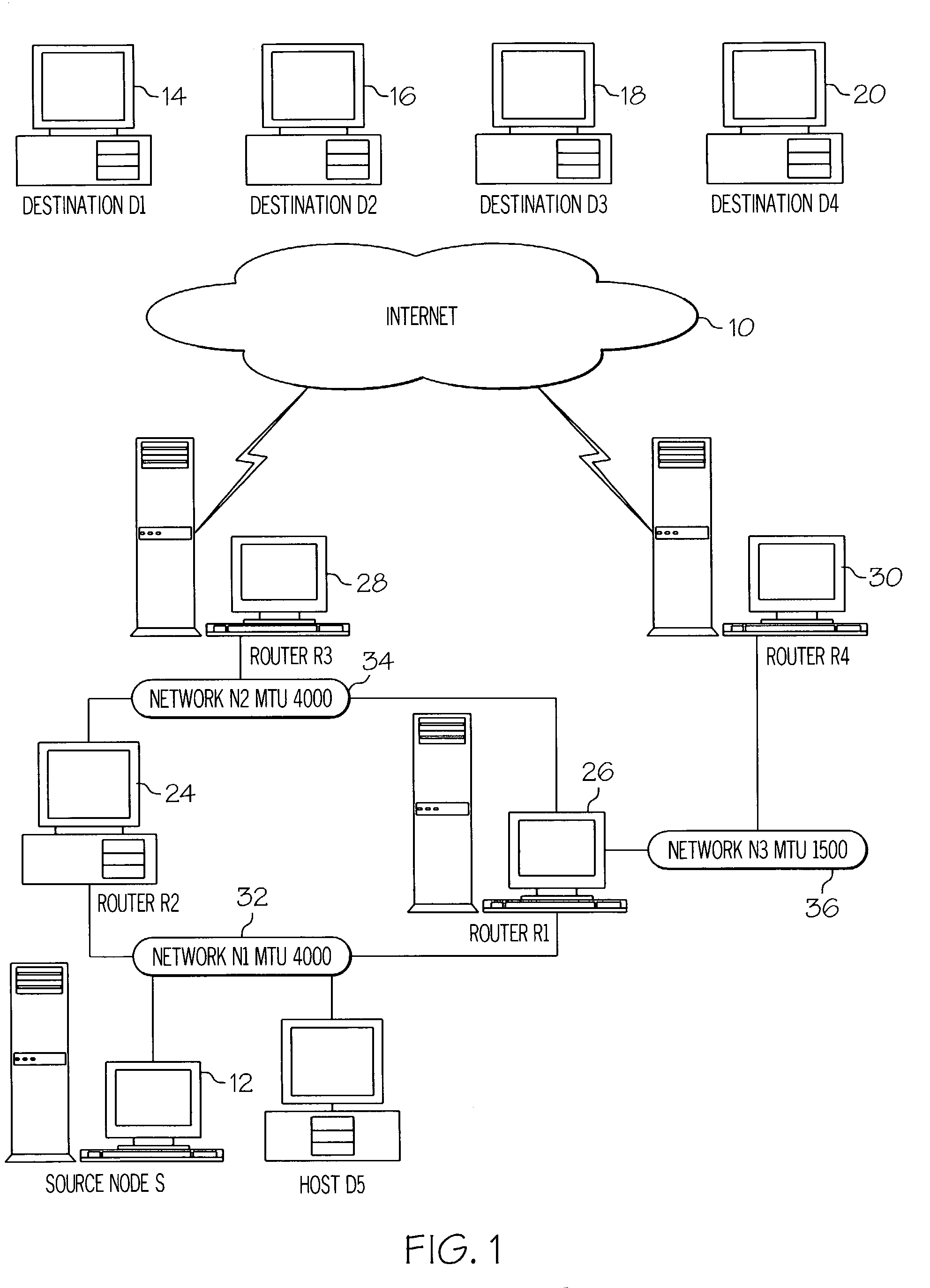
[0039]The following example utilizes FIG. 1, wherein the source node (12) is in communication with destinations D1(14), D2(16), D3(18) and D4(20). As illustrated, these destinations are reachable via three alternative paths. Path 1 comprises router R2(24) and router R3(28). Path 2 comprises router R1(26) and router R4(30). Path 3 comprises router 1(26) and router 3(28). The initial known PMTU for Path 1=4000, for Path 2=1500 and for Path 3=4000.

[0040]A Telnet connection (C1) from the host system (12) to target system D1 (14) utilizes very small TCP packets of approximate size 75 bytes. Another connection (C2) between the host system (12) and target system D2(16) is established to transfer a large file over TCP which will use the maximum available MTU.

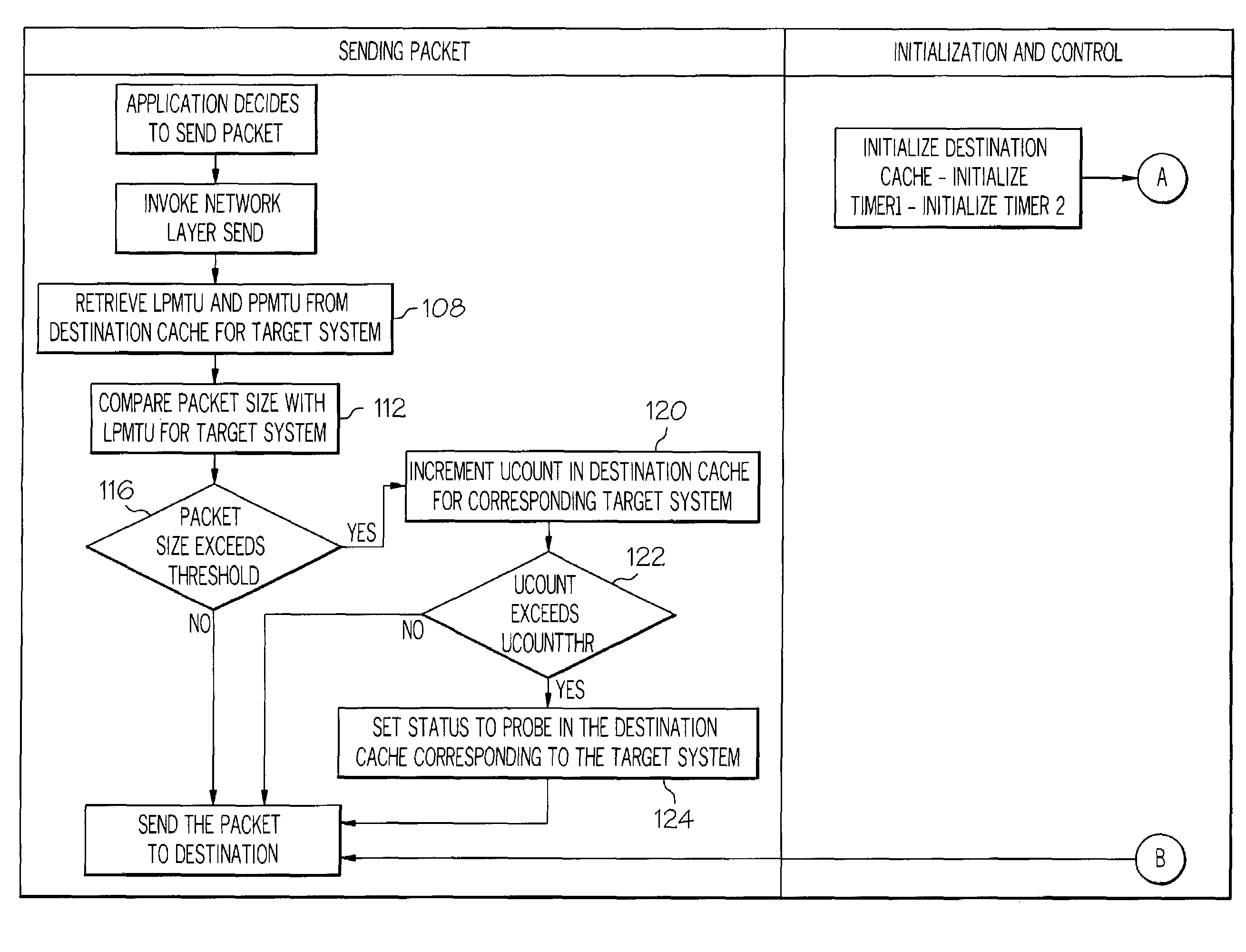
[0041]Timer 1 is initiated and an action alarm is set at 5 minutes for the timer. UCOUNTHR is set to 200. Timer 2 is initiated and an action alarm is set to every 30 seconds for the timer. To start transmission of the data packets, the ...


PUM


Abstract

A method and mechanism for determining when to transmit a probe packet to detect increases in path maximum transmission unit (PMTU) in a network having a host and a target interconnected by the network. Calculate a utility variable corresponding to a number of packets to be transmitted from the host to the target which are greater than a predetermined amount of a known PMTU for the target. When the utility variable is greater than a predetermined utility threshold, sending instructions to the host to send a probe packet to detect increases in PMTU for the target. Storing the previous state of the internet path with respect to PMTU in a variable PPMTU and tracking it during decreases so that a restoration of the PMTU can be verified by sending probes. PMTU is treated as a resource which is either fully or partially used by an application.

Description

FIELD OF THE INVENTION[0001]Embodiments of the present invention relate generally to network communications and, more specifically, to methods and systems for determining when to transmit a probe packet to detect increases in path maximum transmission unit (PMTU) in the network.BACKGROUND OF THE INVENTION[0002]The introduction and increasingly wide usage of computers in the past 30 years has made heretofore unavailable information increasingly accessible. This information or data explosion has increased exponentially in the past decade with the advent of personal computers and the large linking of computers via local and wide area networks. These computers or workstations coupled with each other can transmit many types of information from one geographical location to another geographical location. This information can be in form of voice, video, and data, which have been commonly termed as “multi-media.” Information transmitted over the internet or internet “traffic” has increased d...

Claims


Application Information

Patent Timeline
Patent Type & Authority Patents(United States)
IPC IPC(8): H04L12/26
CPCH04L12/66
Inventor SWAROOP, ASHISHALEX, RAMACHANDRAN NIRMALA
Owner MICRO FOCUS SOFTWARE INC
Why Eureka
Try Eureka