
Seasoning apparatus, and product manufacturing system provided therewith

a technology of seasoning apparatus and product manufacturing system, which is applied in the direction of instruments, applications, transportation and packaging, etc., can solve the problems of short stay time, processing time, and virtually impossible to adjust the seasoning processing time for each individual article in the tumbler

Inactive Publication Date: 2007-12-11
ISHIDA CO LTD
View PDF21 Cites 4 Cited by
  • Summary
  • Abstract
  • Description
  • Claims
  • Application Information

AI Technical Summary

Benefits of technology

This approach ensures that each article is seasoned consistently and uniformly, maintaining the optimal seasoning ratio without over- or under-seasoning, by maintaining a constant seasoning time and ratio throughout the process.

Problems solved by technology

However, that mention is from the overall, average perspective of one cluster of an article group; given the use of a tumbler in the aforementioned structure, it is virtually impossible to adjust the seasoning processing time for each individual article in the tumbler.
As a result, for example, articles that exit earlier from the tumbler have a short staying time in the tumbler, i.e., the seasoning processing time (time in contact with the seasoning) is short, and therefore the seasoning lightens.
On the other hand, the quantity of articles remaining in the tumbler decreases by the quantity of articles that exited earlier in this manner (the seasoning ratio increases), and the seasoning therefore becomes heavy.
However, it is fundamentally unavoidable that, within the articles of that single group, there will be some unevenness in the seasoning, some being heavily seasoned and some being lightly seasoned.
Accordingly, it is difficult to uniformly season each and every article at a prescribed optimal ratio.

Method used


Image

  • Seasoning apparatus, and product manufacturing system provided therewith
  • Seasoning apparatus, and product manufacturing system provided therewith
  • Seasoning apparatus, and product manufacturing system provided therewith

Examples


first embodiment

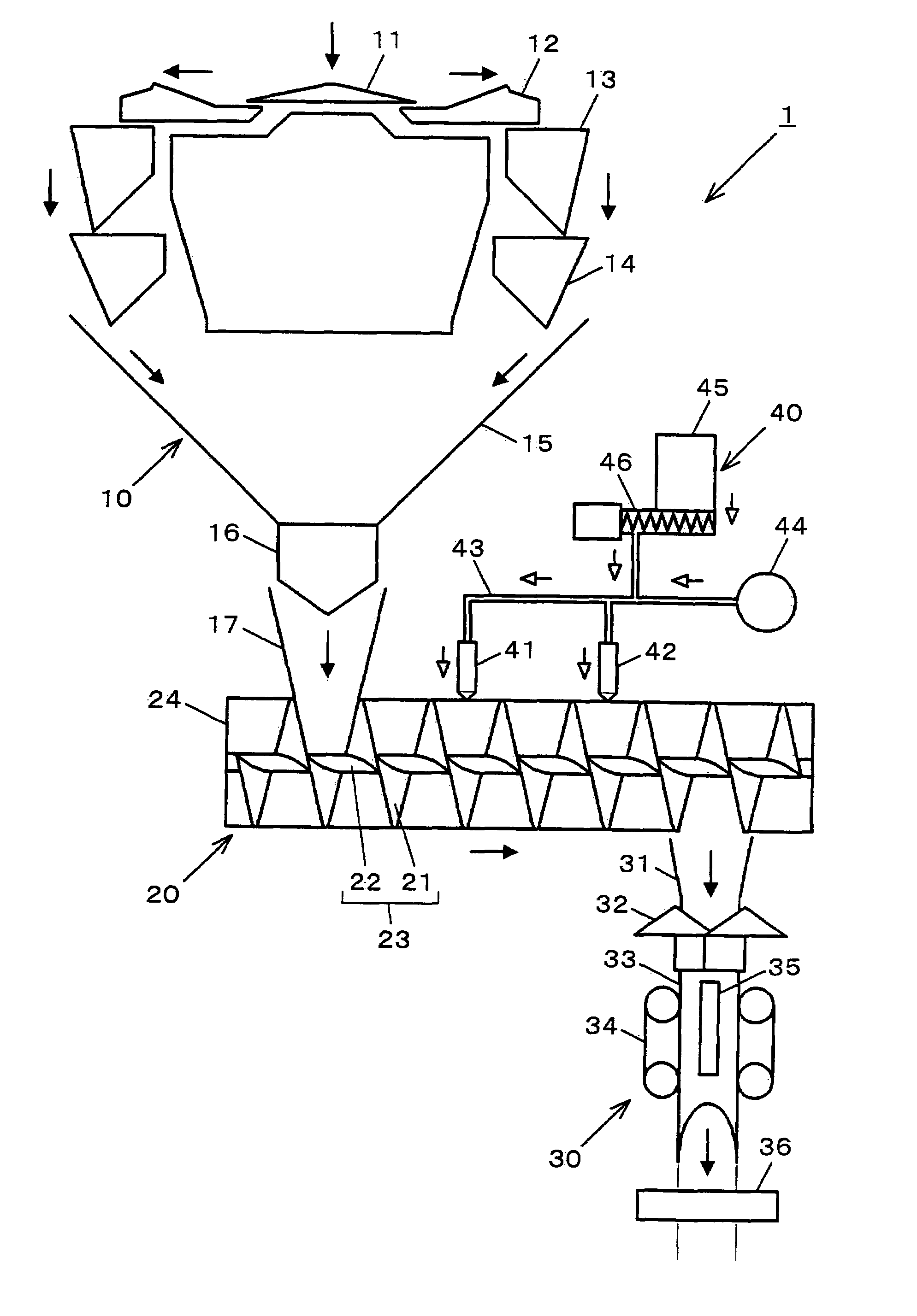
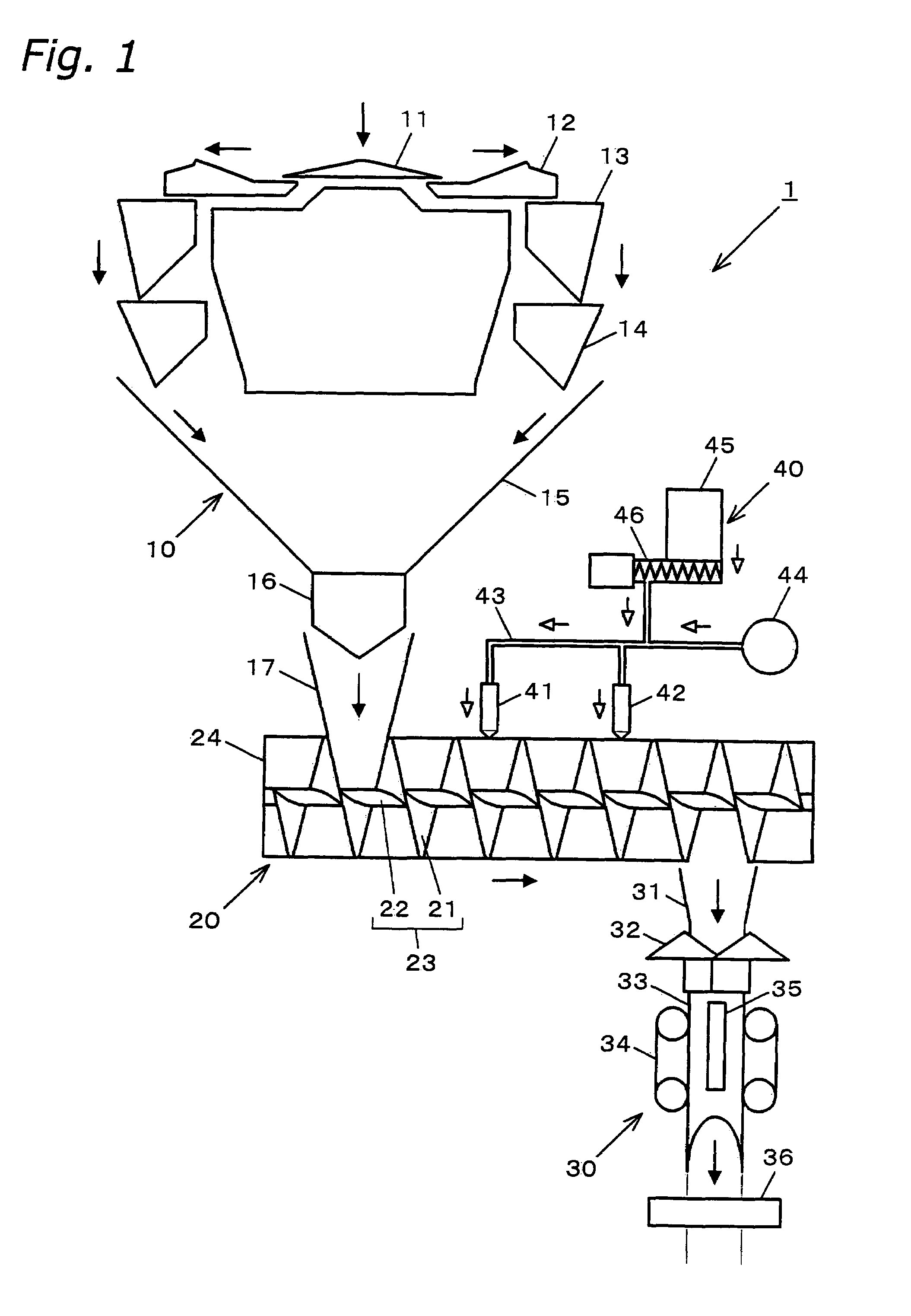
[0113]FIG. 1 is a block diagram of a product manufacturing system 1 provided with a seasoning apparatus 20 according to the present embodiment. The black arrows show the direction of flow of the articles, and the white arrows show the direction of flow of the compressed air and the seasoning. The product manufacturing system 1 weighs, seasons, and packages snacks like potato chips, and includes, in sequence of the direction of the flow of the articles from the upstream side, a weighing apparatus 10 (an example of upstream apparatus), the seasoning apparatus 20, and a packaging apparatus 30 (an example of downstream apparatus).

[0114]The weighing apparatus 10 is a well-known combinational weighing apparatus. Namely, a feeder like a belt conveyor and a bucket conveyor (not shown) supplies a large quantity of articles onto a dispersion table 11 where the articles are dispersed and supplied to a plurality of pool hoppers 13 . . . 13 by a plurality of feeders 12 . . . 12, and are then wei...

second embodiment

[0153]The first embodiment performed all processing of an article group of a single package unit quantity weighed by the weighing apparatus 10 as a single unit. In other words, the entire quantity of the article group X weighed by the weighing apparatus 10 is supplied (for each single package unit quantity) to a single section of the seasoning apparatus 20, transported, seasoned, and transferred to the packaging apparatus 30. In contrast, in the second embodiment, the article group of a single package unit quantity weighed by the weighing apparatus 10 is intentionally divided into a plurality (of article groups), and those divided article groups are supplied as individual units to the sections of the seasoning apparatus 20, transported, seasoned, and transferred to the packaging apparatus 30. However, as discussed later, because it is necessary to once again collect the plurality of article groups into a single article group (into a single package unit quantity) when transferring to...

third embodiment

[0158]In the first embodiment, it is also acceptable to electrically charge at least one of the article group X and seasoning, and to adhere the seasoning to the article group X using that electrostatic function. The seasoning process is thereby completed within a short time period, and seasoning is performed more uniformly without any unevenness. In addition, the remaining unadhered seasoning is reduced (the seasoning adheres with a good yield). However, when both the article group X and the seasoning are electrically charged, they must be mutually charged with differing polarity.

[0159]FIG. 10 shows an electrical charging apparatus 50 capable of being used in the third embodiment. The electrical charging apparatus 50 is arranged between the timing hopper 16 and the intake chute 17 of the weighing apparatus 10, and has a pair of opposing electrodes 51, 52 that interpose the drop pathway of the weighed article group X. One electrode 51 is connected to a high-voltage power supply 53, ...


PUM

PropertyMeasurementUnit
net weightaaaaaaaaaa
rotational angleaaaaaaaaaa

Abstract

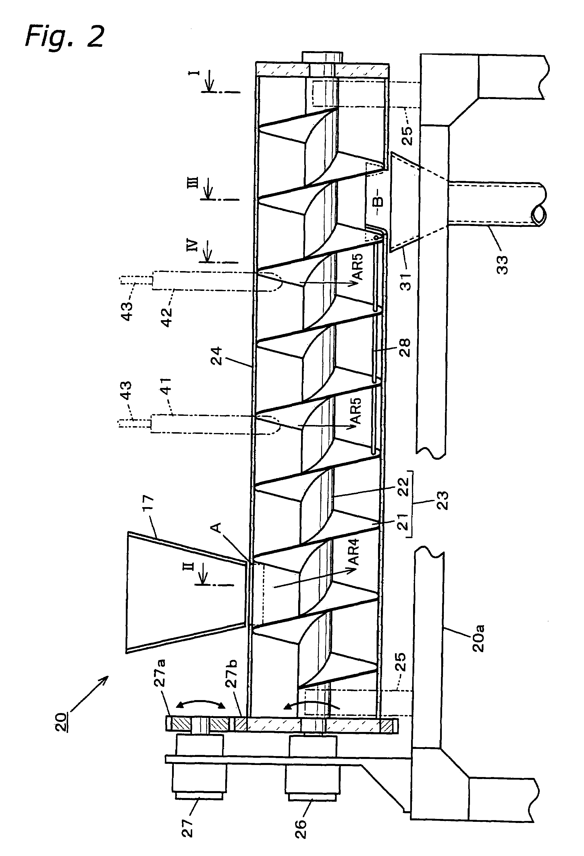
The present invention provides a seasoning apparatus capable of evenly seasoning each individual article, without seasoning any too heavily or too lightly. Therein, a screw having a helical blade is installed in a tube. The helical blade provides partitions that are provided upright between an article supply port and a discharge port. An article group, before seasoning, is accommodated in a section partitioned by the partitions, the motor rotates the screw, and the article group is transported from the supply port to the discharge port. Therein, each article group is transported to the discharge port separated from other article groups, and each individual article in the article group is seasoned evenly with the same seasoning processing time and the same seasoning supply ratio. In addition, the constitution of the seasoning apparatus is simplified because the screw simultaneously serves the two functions of separating and transporting the article groups.

Description

FIELD OF THE INVENTION[0001]The present invention relates to foodstuffs manufacturing, such as the seasoning and transport of articles like snacks.RELATED ART[0002]An example of a production line for snacks like potato chips is disclosed in Examined Japanese Patent Publication No. 4-35132, which discloses a seasoning process implemented using a tubular tumbler with an opening at both ends. Namely, the tumbler is arranged so that the shaft axis is inclined at a prescribed angle, rather than being horizontal, the tumbler is made to rotate around the shaft, and articles are supplied therein from the upper opening. While the articles bounce around due to the rotation of the tumbler, the incline of the tumbler moves the articles downward, and the articles exit the tumbler from the lower opening. At that time, articles are supplied into the tumbler from the upper opening along with seasoning of a quantity commensurate with the quantity of supplied articles. From the time the articles ente...

Claims


Application Information

Patent Timeline
Patent Type & Authority Patents(United States)
IPC IPC(8): B05C19/04B05C13/02B05C19/06A23L19/18A23P1/08A23P20/17
CPCA23P1/084A23P20/17
Inventor KITAGAWA, KAZUMIYAKUSHIGAWA, YASUSHIYOSHIKAWA, TAKAOKOSAKA, AKIRA
Owner ISHIDA CO LTD
Learn More