Flat microwave antenna

a technology of microwave antenna and antenna body, which is applied in the direction of individual energised antenna array, polarised antenna unit combination, stripline fed array, etc., can solve the problems of inacceptable degradation of antenna performance, achieve low antenna height, facilitate installation, and maintain the effect of aerodynamic properties of the vehicl

Active Publication Date: 2007-12-11
GILAT SATELLITE NETWORKS
View PDF10 Cites 38 Cited by
  • Summary
  • Abstract
  • Description
  • Claims
  • Application Information

AI Technical Summary

Benefits of technology

[0005]The objective of the invention is to provide flat microwave antenna with reduced height, while keeping good antenna performance.
[0015]The advantages of the flat microwave antenna according to the present invention are connected with the possibility to achieve a low height of the antenna and to facilitate its installation directly on the roofs of the different moving platforms (like cars, buses, trucks, sport utility vehicles, trains etc.), keeping at the same time aerodynamic properties of the vehicle almost unchanged. The low profile of the antenna is achieved without degradation of the antenna performance and especially antenna's figure of merit.
[0016]Due to the specific arrangement of the radiating apertures and the construction of feed lines, a significant insertion loss reduction in antenna feed layers is achieved. Dividing the antenna into sub-arrays and changing the position of the layers dedicated to different polarizations allow achieving of the signal amplitudes' equalization for two different polarizations at the antenna output.

Problems solved by technology

The disadvantage of the antenna described above is its considerable height, preventing its application on mobile platforms, while any attempt for its height reduction will lead to unacceptable degradation of the antenna performance.

Method used


Image

  • Flat microwave antenna
  • Flat microwave antenna
  • Flat microwave antenna

Examples


Embodiment Construction

OF SPECIFIC IMPLEMENTATION

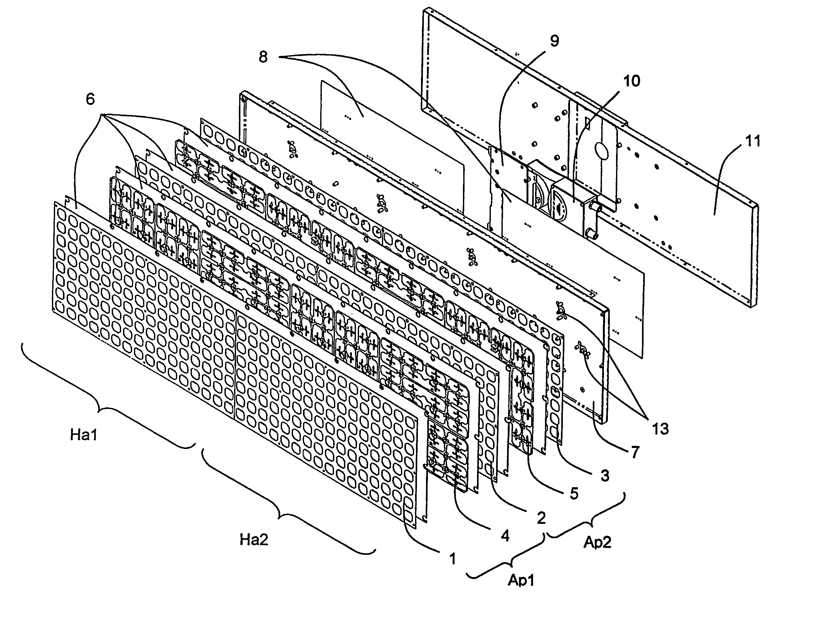
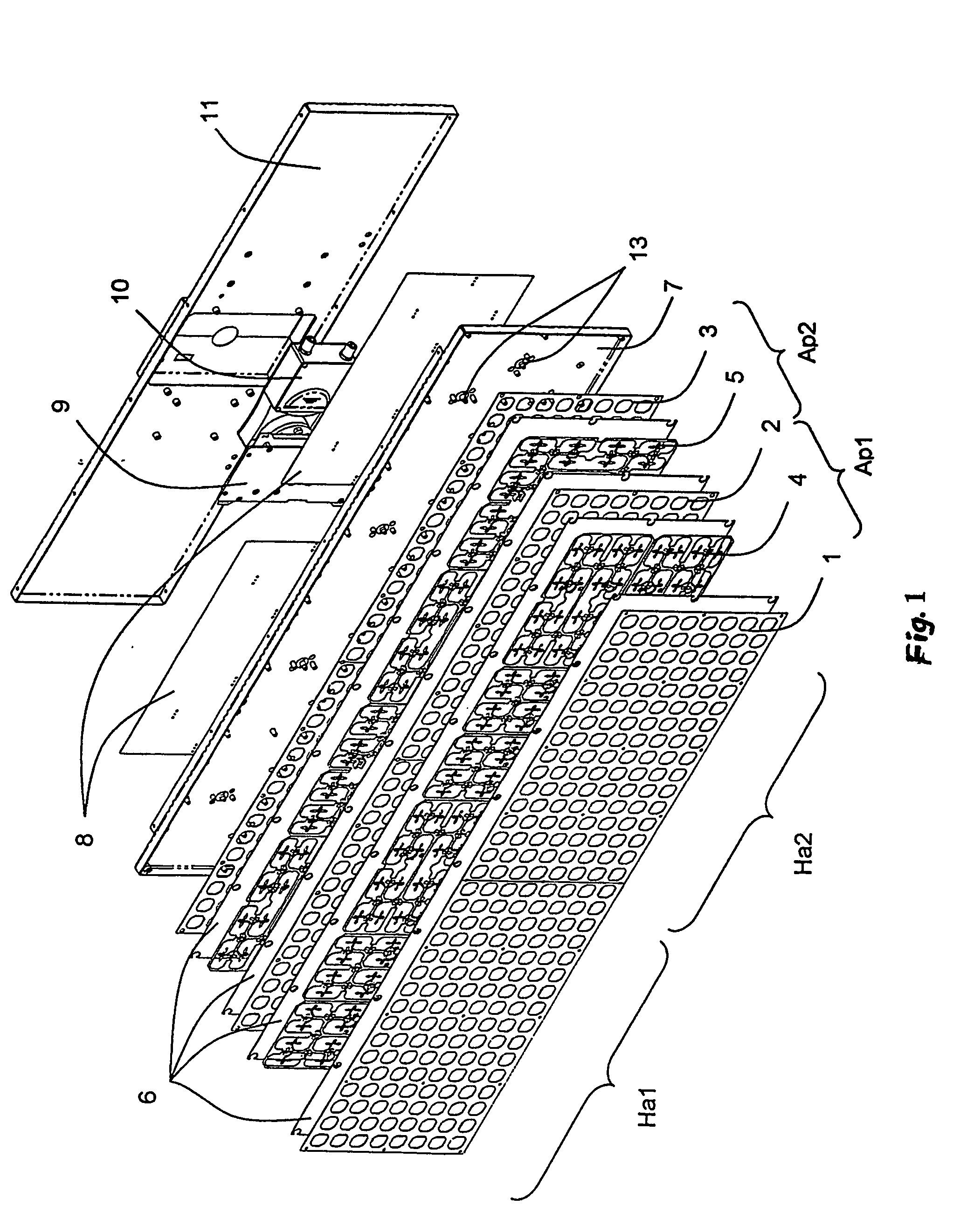
[0026]The example refers to the preferred application, namely planar active antenna 1-13 (shown in FIG. 1) as a part of a system for in-motion signal reception from satellite on geo-stationary orbit. Hence, the preferred shape of the antenna is rectangular in order to decrease the overall height of the whole system.

[0027]The antenna consists of a high number of radiating elements arranged in rows and columns at appropriate distance and forming antenna array.

[0028]The distance between adjacent elements is about 0.7 to 0.9 wavelengths in free space for the antenna frequency band of operation, e.g. Ku-band (10.7-12.75 GHz).

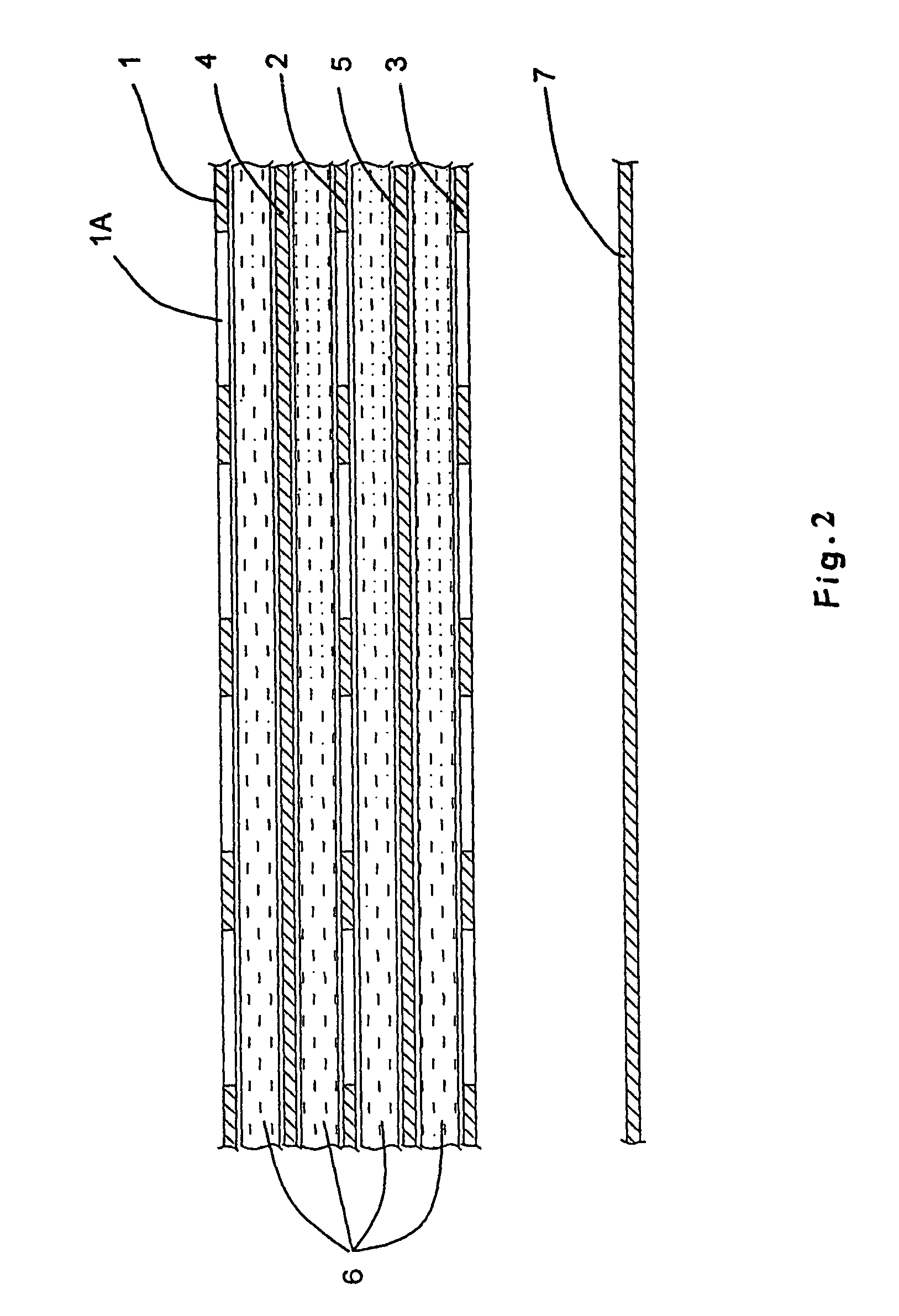
[0029]The antenna shown on FIG. 1 consists of two separate packages Ap1 and Ap2 for two orthogonal polarizations, layer 8 with low-noise amplifiers used for pre-amplification of the received signal, and block 9 for signal combining. As shown in FIG. 2 the antenna layers 4 and 5 are placed between three grounded metal plates 1, 2 and 3 with p...


PUM


Abstract

An antenna has stacked grounded metal plates with openings (1, 2, 3) and antenna layers (4, 5) with feed lines (4B, 5B), situated between grounded metal plates. The openings in the grounded metal plates are arranged as matrix of columns and rows. The ends of the feed lines (4D, 5D) are aligned with the plate's openings (1A) in order to form radiating elements. The plate (7) is placed below the bottom grounded plate (3). The three-plate stack is arranged as two antenna packages (Ap1 and Ap2). These packages include also a layer (8) comprising active devises for initial amplification of the received signal, which are connected to the groups of radiating elements (4D, 5D, 1A) through coaxial transitions (13). As well as a combiner block (9) is connected to the active layer (8). The antenna layers (4, 5) are arranged in subarrays and the antenna output is connected by a transition (12) to a standard twin Low Noise Block.

Description

[0001]This application is a National Stage application of co-pending PCT application No. PCT / BG2004 / 1000011 filed 6 Jul. 2004, which was published in the English language under PCT Article 21(2) on 13 Jan. 2005, and claims the benefit of the Bulgarian Application No. 107973 filed 7 Jul. 2003, these applications are incorporated herein by reference in their entireties.FIELD OF THE INVENTION[0002]The present invention refers to a flat microwave antenna applicable to mobile communication systems for satellite signal reception from satellites arranged on geostationary orbit.BACKGROUND OF THE INVENTION[0003]U.S. Pat. No. 5,872,545 discloses a multi-plate stack type microwave antenna, comprising a set of slot radiating elements arranged as a matrix of columns and rows. The basic antenna package consists of three plates with openings and two plates comprising feed lines that allow the forming of two receiving beams having a specified angle between them. Antenna includes also at least anoth...

Claims


Application Information

Patent Timeline
Patent Type & Authority Patents(United States)
IPC IPC(8): H01Q1/38H01Q21/00H01Q21/06H01Q21/24
CPCH01Q21/0075H01Q21/0081H01Q21/24H01Q21/064H01Q21/061
Inventor PESHLOV, VESSELIN NIKOLOVTRAYKOV, ROSSEN NIKOLOV
Owner GILAT SATELLITE NETWORKS
Why Eureka
Try Eureka