
Seismic modem

a modem and modem technology, applied in the field of data communication, can solve the problems of affecting the operation of the modem,

Inactive Publication Date: 2007-12-11
GULA CONSULTING LLC
View PDF28 Cites 20 Cited by
  • Summary
  • Abstract
  • Description
  • Claims
  • Application Information

AI Technical Summary

Benefits of technology

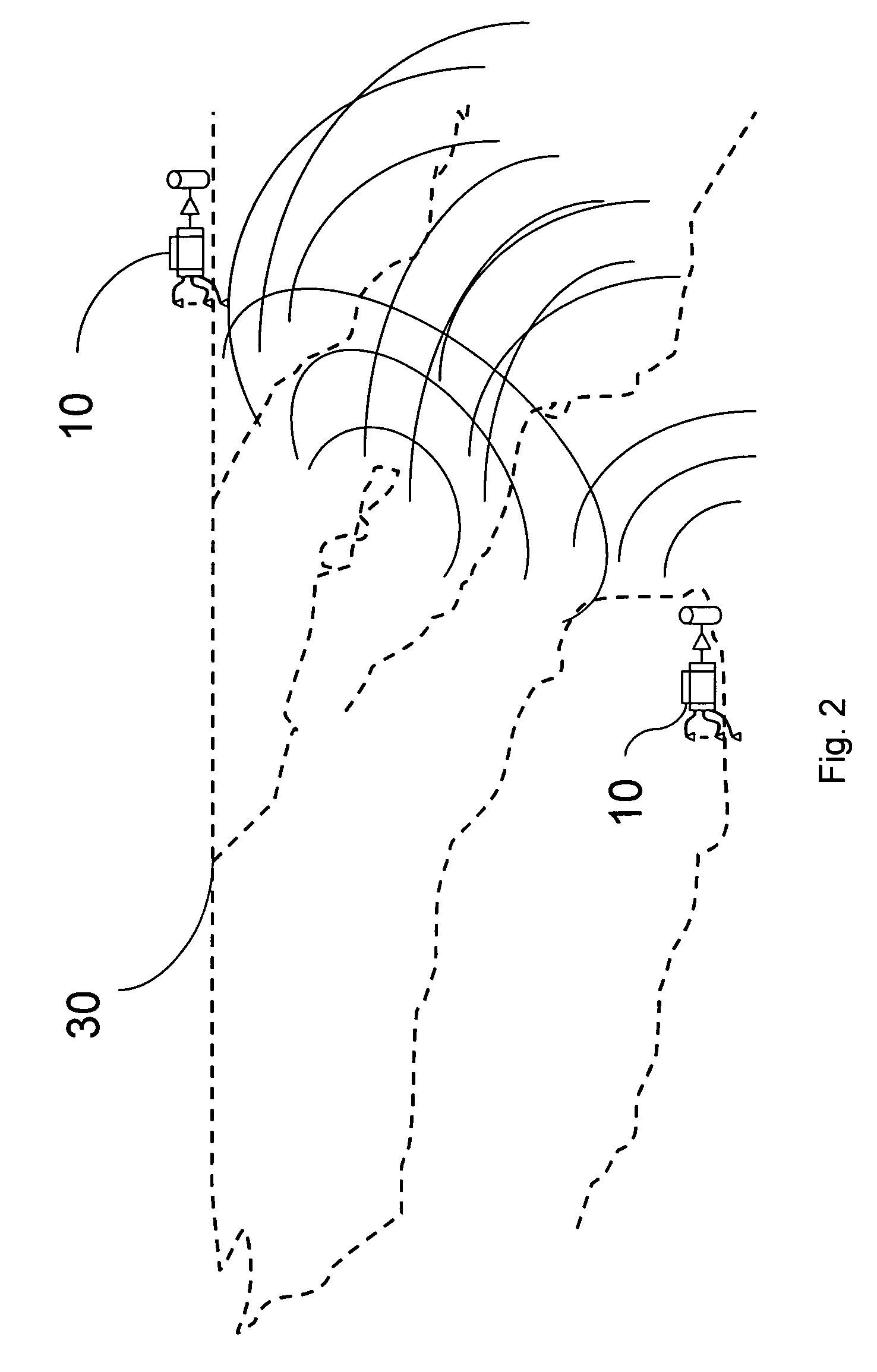
The present invention provides a system for transmitting data by seismic waves using a transmitting unit and a receiving unit. The transmitting unit encodes and amplifies a signal, and the receiving unit receives the signal and identifies it. The system can be used in various applications such as oil and gas exploration, and can be integrated into footwear or other devices. The invention also provides methods for transmitting and receiving seismic waves, as well as apparatus for communication by seismic waves. The technical effects of the invention include improved data transmission speed and accuracy, as well as increased flexibility and portability of seismic wave transmission devices.

Problems solved by technology

Often instruments and sensors are placed in locations where radio communications are impossible or impractical.
Cave walls, walls of narrow gorges and other geological features may block radio transmissions which might otherwise be used to monitor or communicate with such instruments.
Often, the physical location of the instruments means that cables to such instruments must be long.
Such installations are awkward and time consuming.
Such long cables are vulnerable to damage.

Method used


Image

  • Seismic modem
  • Seismic modem
  • Seismic modem

Examples


Embodiment Construction

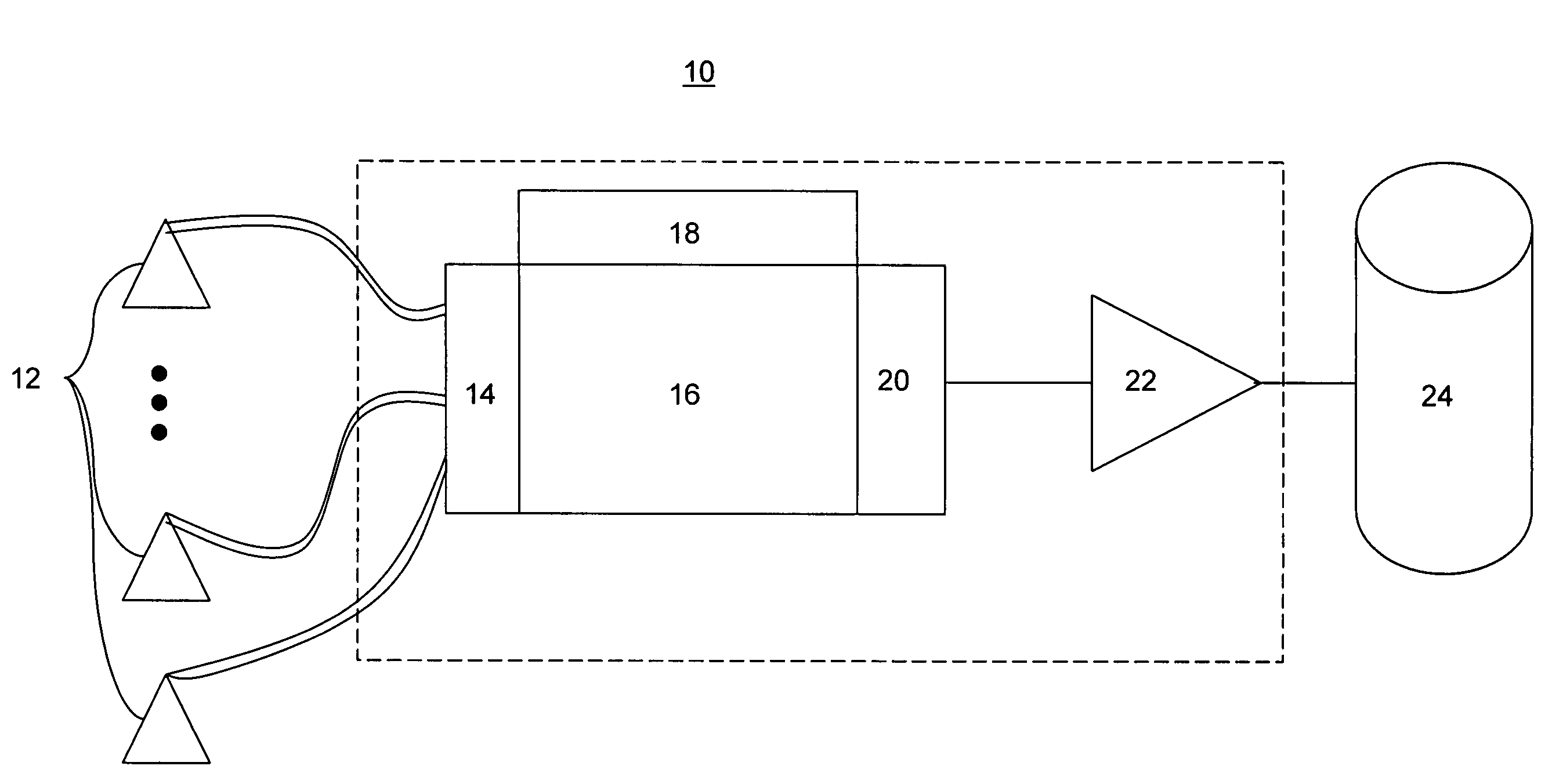
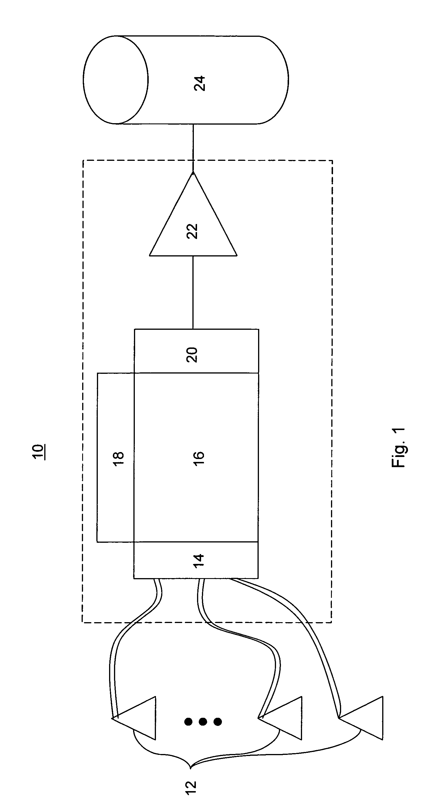
[0034]In one embodiment of the present invention, illustrated in FIG. 1, a seismic modem 10 is provided, comprising at least one geophone 12, coupled, via an A / D converter 14, to a processor 16 having an instrument interface 18, which is in turn coupled via a D / A converter 20 to an amplifier 22 communicating with a seismic inducer 24. In some embodiments one or more geophones may be provided forming an array of geophones. One skilled in the art will readily appreciate that microphones may be used in place of geophones 12, affording a broader frequency spectrum.

[0035]The modem of FIG. 1, in one embodiment operates according to the method illustrated in the flow chart of FIG. 3. Data is received by the modem 10 from a machine or a user through an interface 18. The received data is encoded and modulated by a processor 16, and passed through a D / A (Digital to analog) converter 20. The analog signal is amplified by the amplifier 22 and passed to the wave inducer 24 which then converts th...


PUM


Abstract

A system for the transmission of data by seismic wave, the system having at least one transmitting unit, that at least one transmitting unit comprising a first processing unit encoding a first signal, the first processing unit being coupled to a digital to analog converter, an amplifier amplifying the first signal, and a seismic pressure wave inducer transmitting the first signal to a geological feature; and at least one receiving unit, the receiving unit comprising at least one receiver coupled to the geological feature for receiving the first signal, and an analog to digital converter whereby the first signal is transferred from the geophone and is conveyed to a second processing unit, the second processing unit being configured to identify and decode the first signal.

Description

FIELD OF THE INVENTION[0001]The invention relates to data communications, and more particularly, to a data communications channel using seismic pressure waves.BACKGROUND OF THE INVENTION[0002]Often instruments and sensors are placed in locations where radio communications are impossible or impractical. Cave walls, walls of narrow gorges and other geological features may block radio transmissions which might otherwise be used to monitor or communicate with such instruments. Known techniques for monitoring such instruments require installation of cables. Often, the physical location of the instruments means that cables to such instruments must be long. Such installations are awkward and time consuming. Such long cables are vulnerable to damage.[0003]In some fields, especially in energy prospecting, seismic charges and waves have been used to communicate information. These techniques often rely on time intervals between nearly identical seismic shots, in essence, these techniques are a...

Claims


Application Information

Patent Timeline
Patent Type & Authority Patents(United States)
IPC IPC(8): H04B11/00
CPCH04B11/00
Inventor KIMBALL, STEVEN F
Owner GULA CONSULTING LLC
Learn More