Modular welding equipment

a technology of welding equipment and modules, applied in the direction of auxiliary welding devices, forging/hammering/hammering apparatuses, forging/hammering/pressing machines, etc., can solve the problems of not being able to manufacture other parts, economic loss from scrapping the entire machine, and not providing any means for positively latching the tooling module, etc., to achieve the effect of facilitating switching

Active Publication Date: 2007-12-18
TEC OPTION
View PDF16 Cites 6 Cited by
  • Summary
  • Abstract
  • Description
  • Claims
  • Application Information

AI Technical Summary

Benefits of technology

[0011]According to yet another aspect of this invention, there is provided a method of operating a welding machine using a user interface that permits modular programming of one or more operational sequences of welding machine valves and weld operations for a variety of different tooling modules. The method facilitates switching over to a different tooling module wherein an operator inputs a new sequence of operations using the user interface rather than rewriting ladder logic.

Problems solved by technology

In this practice, especially in connection with resistance and MIG welding machines, each machine is dedicated to the manufacture of a particular part and is not usable for manufacture of other parts.
Previously, there had been a longstanding need in the industry to overcome the disadvantages which accompany the practice of using dedicated welding machines such as the economic loss from scrapping the entire machine when the tools and fixtures are no longer usable because of wear and tear or because of termination of production of the part to which the machine is dedicated.
Additionally, this arrangement does not provide any means for positively latching the tooling module to the tooling cart to maintain the tooling module in place and prevent the tooling module from shifting on the cart as the tooling cart is moved.

Method used


Image

  • Modular welding equipment
  • Modular welding equipment
  • Modular welding equipment

Examples


Embodiment Construction

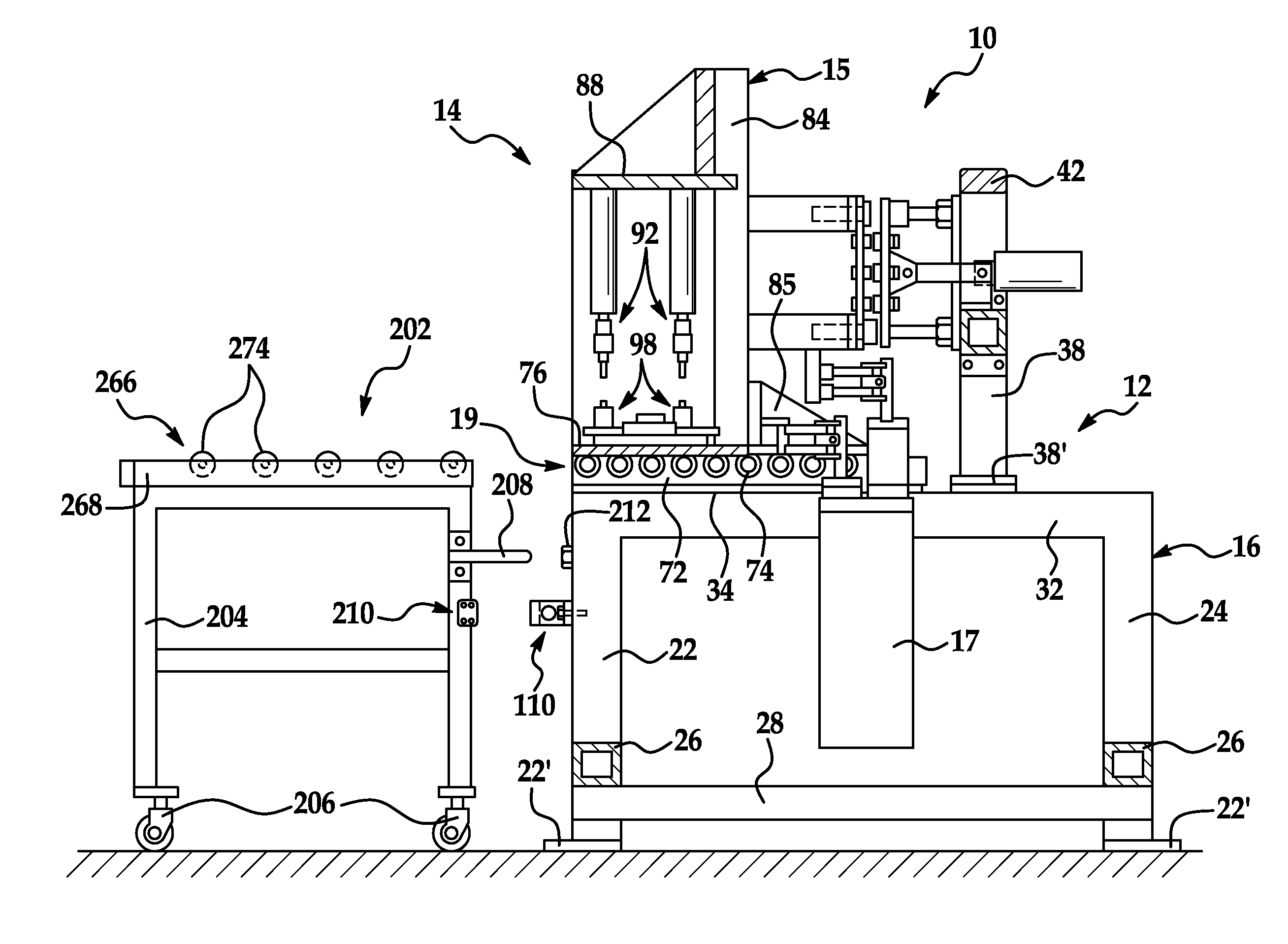
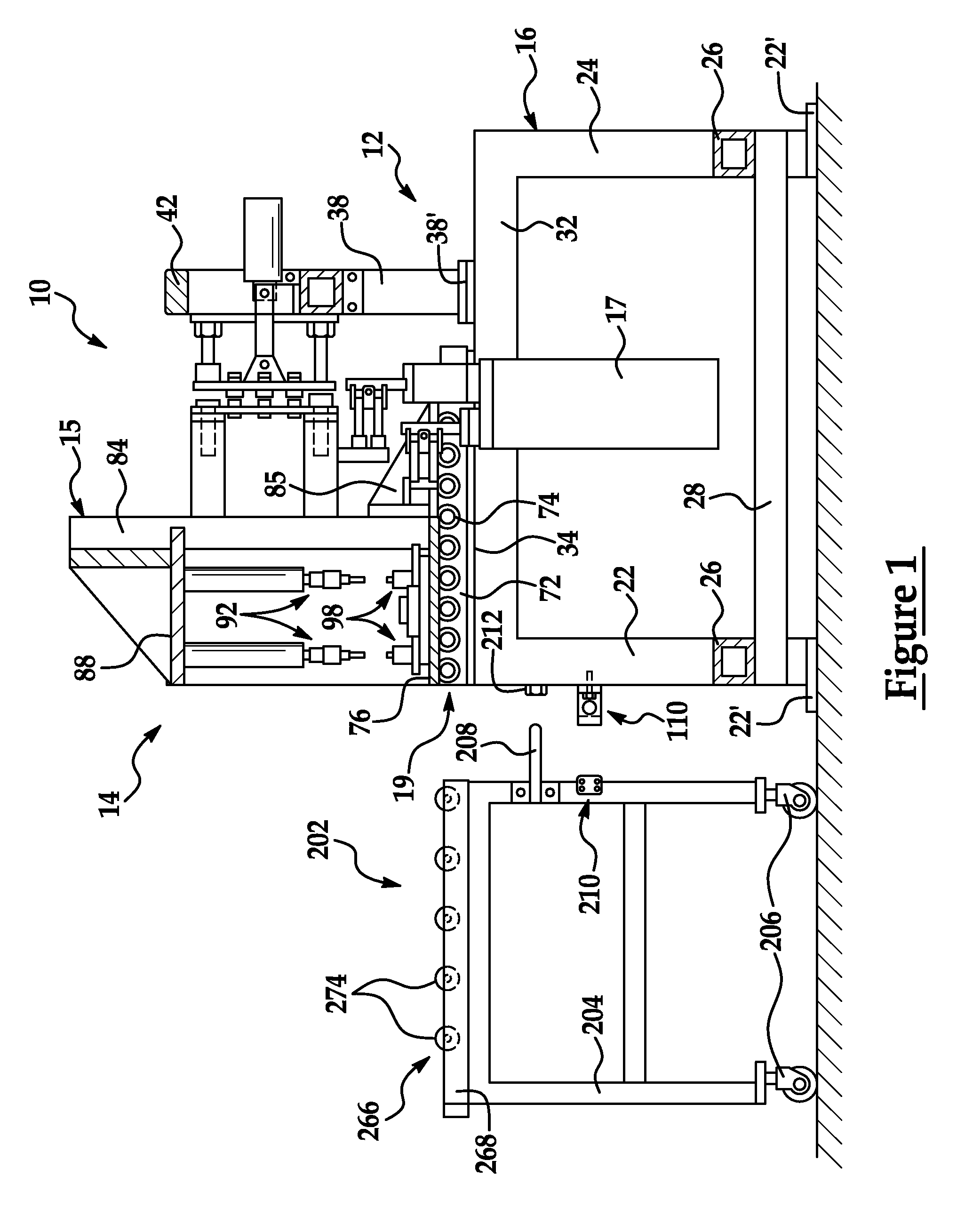
[0022]The description that follows will set forth the best mode for carrying out the invention by describing illustrative embodiments of the inventive modular welding machine as presently contemplated. This invention is especially adapted for use with electric welding machines of all types, but can be used in conjunction with other types of welders. This disclosure relates to various improvements to the modular welding machine disclosed in U.S. Pat. No. 6,512,195, which is assigned to the assignee hereof and which is incorporated by reference herein in its entirety. It will be appreciated as the description proceeds that the invention is useful in a wide variety of applications and may be realized in many different embodiments.

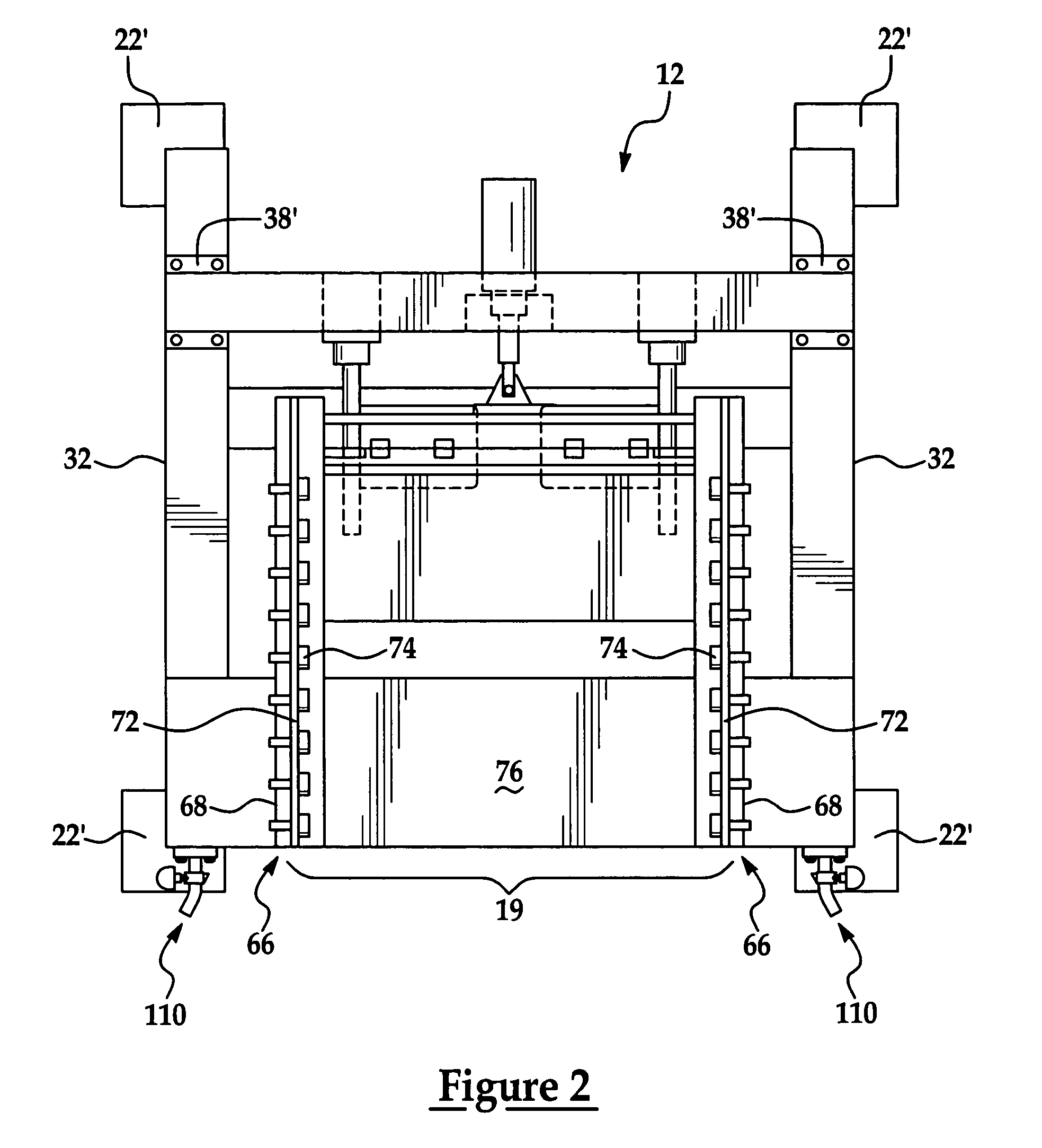
[0023]Referring now to FIGS. 1 and 2, an exemplary embodiment of modular welding equipment according to this invention includes a welding machine 10, which is a resistance welder of the spot welding type. The welding machine 10 comprises, in general, a base op...


PUM

PropertyMeasurementUnit
bias forceaaaaaaaaaa
resistanceaaaaaaaaaa
cylindrical shapeaaaaaaaaaa

Abstract

Welding equipment that includes a tooling cart for transferring interchangeable tooling modules to a welding machine. A latch is mounted to the welding machine for latching the tooling cart to the welding machine, and a latch is provided for latching the tooling modules onto the tooling cart. A two-piece tooling cart includes a removable upper section for securing tooling modules thereto and a reusable lower section for use with other tooling modules. A welding method permits operation of a welding machine using a user interface that permits modular programming of at least one operational sequence of welding machine valves and weld operations for a variety of different tooling modules. An operator inputs a new sequence of operations using the user interface rather than having to rewrite ladder logic just to switch over the welding machine to use with a different tooling module.

Description

CROSS-REFERENCE TO RELATED APPLICATION[0001]This application claims the priority of U.S. Provisional Application No. 60 / 520,062, filed Nov. 15, 2003, the complete disclosure of which is hereby incorporated by reference.FIELD OF THE INVENTION[0002]This invention relates to welding equipment of the type used in manufacturing plants for production of welded parts. More particularly, it relates to electric welding machines, such as resistance welders and metal-inert gas (MIG) welders, and related equipment.BACKGROUND OF THE INVENTION[0003]It has been a common practice in the welding machine industry to build welding machines with custom tooling as an integral part of the welding machine. In this practice, especially in connection with resistance and MIG welding machines, each machine is dedicated to the manufacture of a particular part and is not usable for manufacture of other parts. The working area of such a dedicated machine includes an attached assembly of fixtures and tools specif...

Claims


Application Information

Patent Timeline
Patent Type & Authority Patents(United States)
IPC IPC(8): B23K9/32B23K11/36
CPCB23K9/32B23K37/0294B23K11/36
Inventor DOMSCHOT, BRYAN W.
Owner TEC OPTION
Why Eureka
Try Eureka