Method and apparatus for determining the errors of a multi-valued data signal that are outside the limits of an eye mask

Inactive Publication Date: 2007-12-18
TEKTRONIX INC
View PDF4 Cites 29 Cited by
  • Summary
  • Abstract
  • Description
  • Claims
  • Application Information

AI Technical Summary

Benefits of technology

[0011]An object of the present invention is to provide a method and apparatus for identifying a plurality of errors of a multi-valued data signal that occur outside the boundaries of an

Problems solved by technology

In recent years, the performance of a high-speed communication facility or device has risen to a point that the ability of accurately measuring its quality has become an ever-increasing challenge.
In the area of data communication devices, for example, efforts to reduce size and power while increasing the throughput of a device has increased the possibility of error.
Even though bit error rate testing (BER) is a relatively significant measure of performance, merely measuring the error rate of a high speed communications device or system does not provide enough data to characterize the behavior of a communications channel, device or system.
For production or manufacturing environments, generating a comprehensive series of tests that incorporates generating an eye diagram for each new component or communications subsystem is too costly and quite time consuming.
If the data signal from the target device or subsystem does not deviate very many times into one or more of the zones, thereby producing only a limited number of mask violations, it is likely that the target device or subsystem will have little or no trouble operating properly and meeting or succe

Method used


Image

  • Method and apparatus for determining the errors of a multi-valued data signal that are outside the limits of an eye mask
  • Method and apparatus for determining the errors of a multi-valued data signal that are outside the limits of an eye mask
  • Method and apparatus for determining the errors of a multi-valued data signal that are outside the limits of an eye mask

Examples


Embodiment Construction

[0020]The present invention will now be described in greater detail with reference to the accompanying drawings, in which the preferred embodiments of the invention are shown. The present invention may, however, be embodied in many different forms and should not be construed as limited to the embodiment set forth herein; rather these embodiments are provided so that this disclosure will be thorough and complete and will fully convey the invention to those skilled in the art.

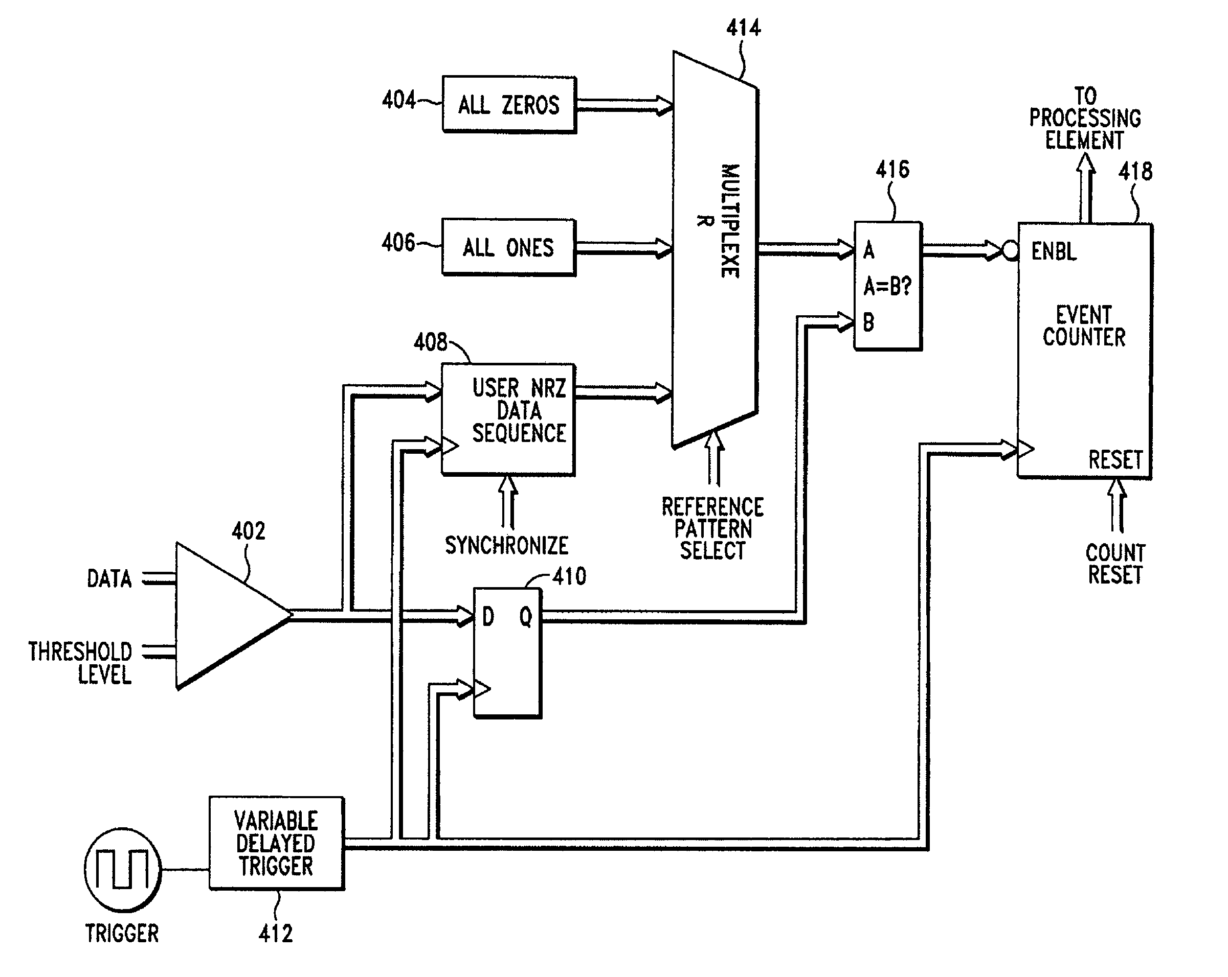
[0021]The invention will now be described illustrating a method and apparatus used to measure and display the number of times a multi-valued data signal transmitted from either a communication device of subsystem deviates across the boundaries and into one or more bounded areas or zones as defined by an eye mask that has been overlaid onto an eye diagram. Unlike the prior art, the present invention employs an iterative process to accumulate and display mask violation that might result from a data signal transmitt...


PUM


Abstract

Disclosed herein is a method and apparatus used to measure the number of time a multi-valued data signal transmitted from either a communication device of subsystem deviates across and into one or more bounded areas or zones as defined by an eye mask that is overlaid onto an eye diagram. The present invention employs an iterative process to accumulate and display mask violation that might result from a data signal transmitted from a target device or communications subsystem that deviates across the boundaries either above or below or into the center of the eye diagram. In addition, the present invention also has the ability to isolate particular threshold voltage-delay points along the boundaries above or below and around the perimeter of the mask polygon of the eye diagram where mask violations have occurred. This provides the ability to supply additional information and feedback about the behavior and performance of the targeted device or subsystem being tested.

Description

BACKGROUND OF THE INVENTION[0001]1. Field of the Invention[0002]This invention relates to systems that measure the performance of a high-speed data communications channel. More precisely, the preferred embodiment of the present invention is a method and apparatus for identifying a plurality of errors of a multi-valued data signal that occur outside the boundaries of an eye mask as defined by regions above, below and in the center of an eye diagram.[0003]2. Description of the Related Art[0004]In recent years, the performance of a high-speed communication facility or device has risen to a point that the ability of accurately measuring its quality has become an ever-increasing challenge. In the area of data communication devices, for example, efforts to reduce size and power while increasing the throughput of a device has increased the possibility of error. Network suppliers, integrators and users want assurances that these devices will perform reliably and can accommodate data transmi...

Claims


Application Information

Patent Timeline
IPC IPC(8): H03D1/00H04L27/06H04L1/24H04L25/03
CPCH04L25/03343H04L1/24
Inventor WASCHURA, THOMAS EUGENEWASCHURA, JAMES R.THANDAPANI, SENTHIL KUMAR
Owner TEKTRONIX INC
Why Eureka
Try Eureka