
Gas water heater damper/baffle

a technology for water heaters and dampers, which is applied in the direction of water heaters, furnace-tube steam boilers, heat exchange apparatus, etc., can solve the problems of large energy losses through exhaust flues, affecting the efficiency of heat exchange,

Inactive Publication Date: 2007-12-25
SCHIMMEYER WERNER K
View PDF14 Cites 10 Cited by
  • Summary
  • Abstract
  • Description
  • Claims
  • Application Information

AI Technical Summary

Benefits of technology

"The patent describes an apparatus for proving the efficiency of a water heater. It includes a base and a damper assembly with movable dampers that can be opened and closed to control the flow of air. The damper assembly is designed to prevent ambient air from flowing through the flue and to direct the flow of exhaust gases from the burner against the flue wall for better heat transfer. The apparatus also includes a heat transfer baffle that is positioned within the flue to further enhance heat transfer. The baffle is made of a tapered tube with three segments that improve heat transfer between the combustion gases and the water tank flue. The technical effects of this apparatus include improved heat transfer, better flue protection, and more efficient water heating."

Problems solved by technology

A water heater damper is important in that energy losses through an exhaust flue can be significant; it is estimated that approximately 33% of the heat energy generated from the main burner and pilot light operation is lost directly up the flue.
While effective for that purpose, such devices often require significant exhaust flow in order to open, and thus are useable only with relatively large units, or those equipped with a fan or blower.
Unfortunately, such systems are too costly and cumbersome for widespread domestic use
Unfortunately, while this system is effective in restricting the circulation of cool room air through the water heater, the long-term operation thereof may result in impaired movement of the poppet due to condensation and debris accumulating between the poppet and the central guide, thus inhibiting the free movement of the poppet along the guide.
Additionally because of the fragile, lightweight nature of the poppet, damage may occur thereto by handling of the device during installation, cleaning or maintenance thereof.
Although the floating poppet closure provides a substantial improvement over the prior art, the shape of the poppet tends to interrupt the vertical flow of exhaust gases, and deflects the flow away from a vertical direction.

Method used


Image

  • Gas water heater damper/baffle
  • Gas water heater damper/baffle
  • Gas water heater damper/baffle

Examples


example

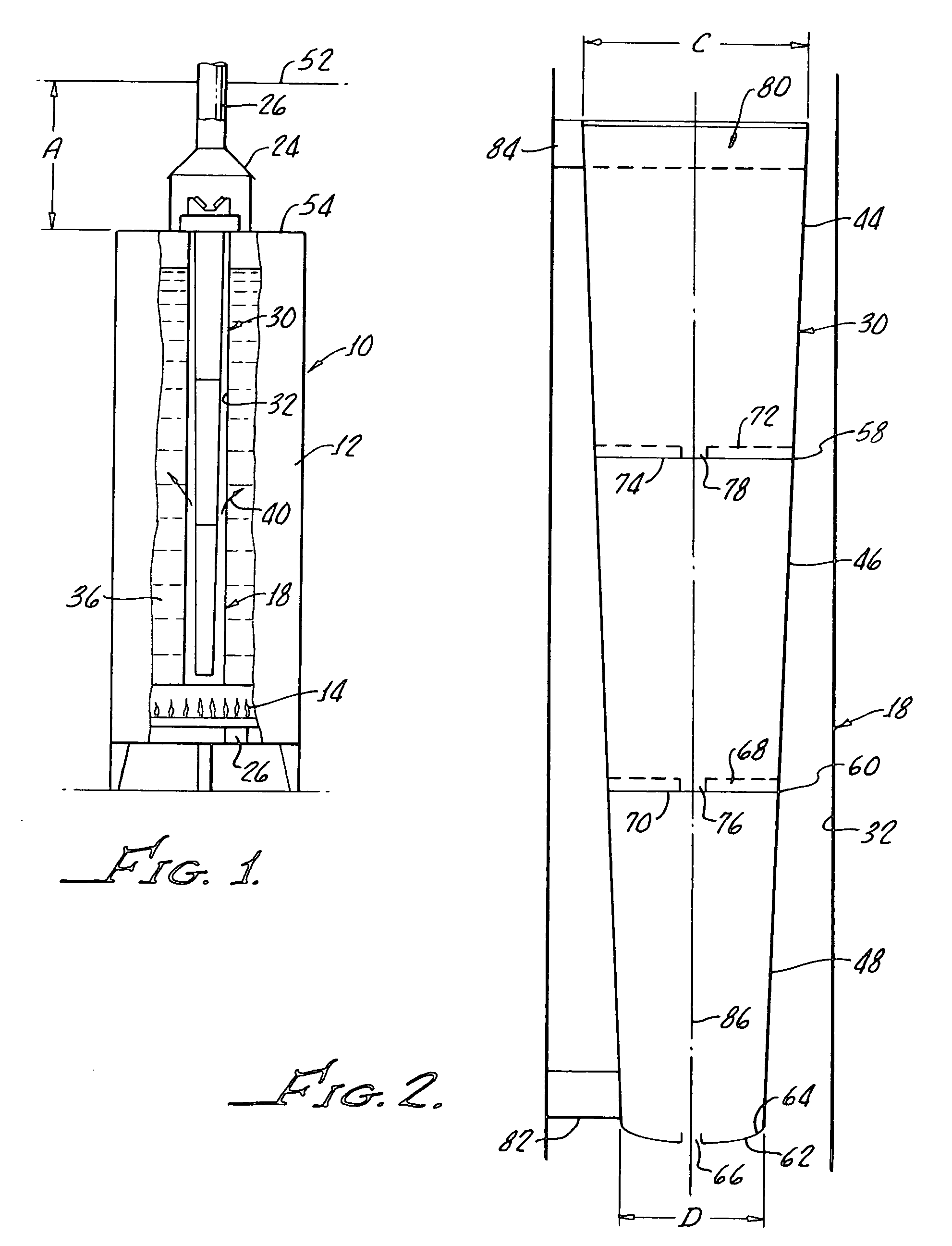
[0044]In a 40 gallon gas fired water heater 10 with the baffle described in U.S. Pat. No. 5,682,841, the control setting was moved from a vacation setting to a normal hot water temperature after withdrawal of 5 gallons of hot water. The recovery time for the heater 10 to bring the water temperature to the set temperature was 5 minutes.

[0045]In a comparative test, the baffle described by U.S. Pat. No. 5,682,841 was removed in a baffle in accordance with the present invention installed into the water heater and the heater moved from a vacation to the same set temperature. The recovery time was 3 minutes and 30 seconds. This is about a 30% reduction in time or savings of 23% of gas usage, which is certainly unexpected in view of the shape difference between the two baffles.

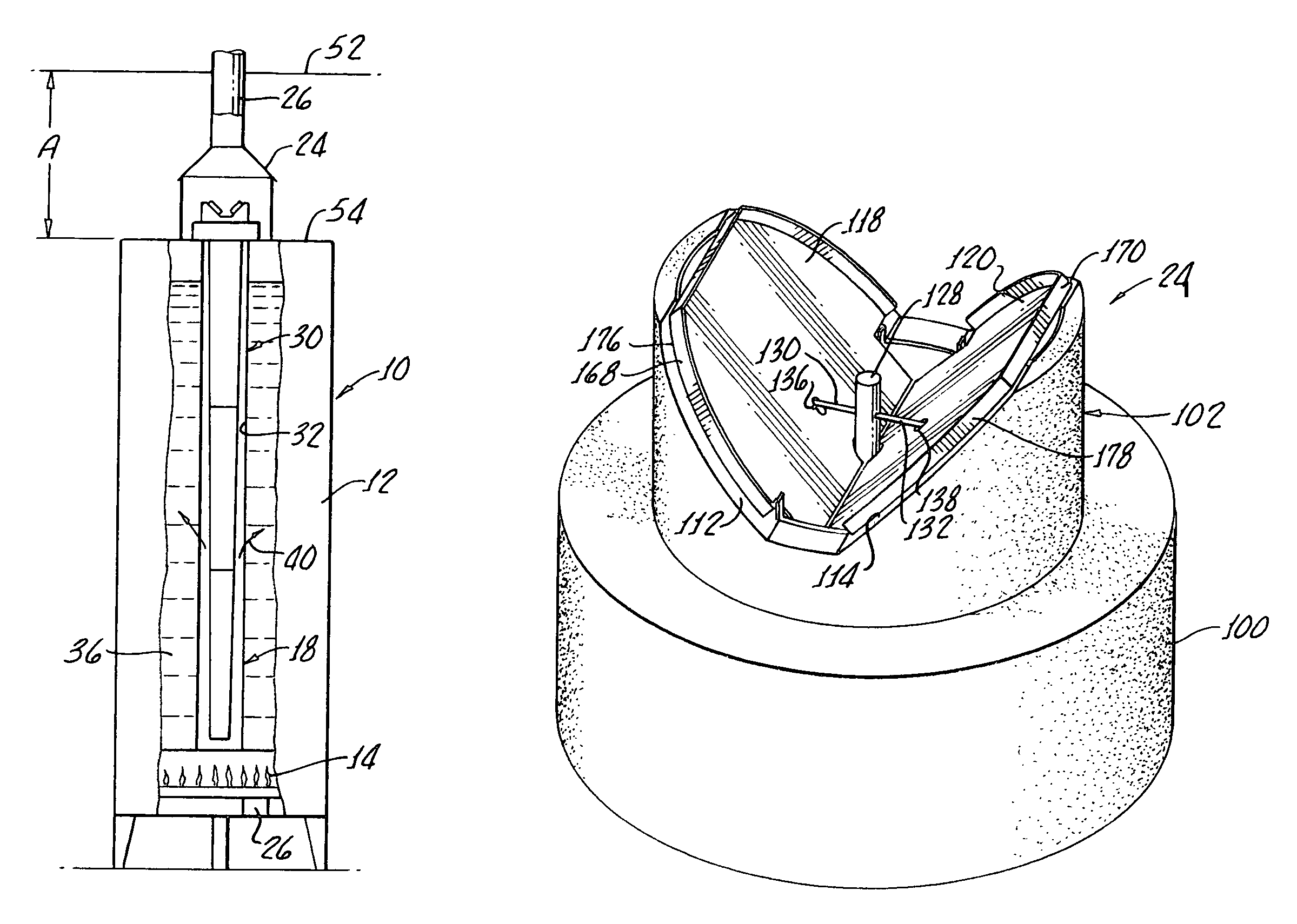
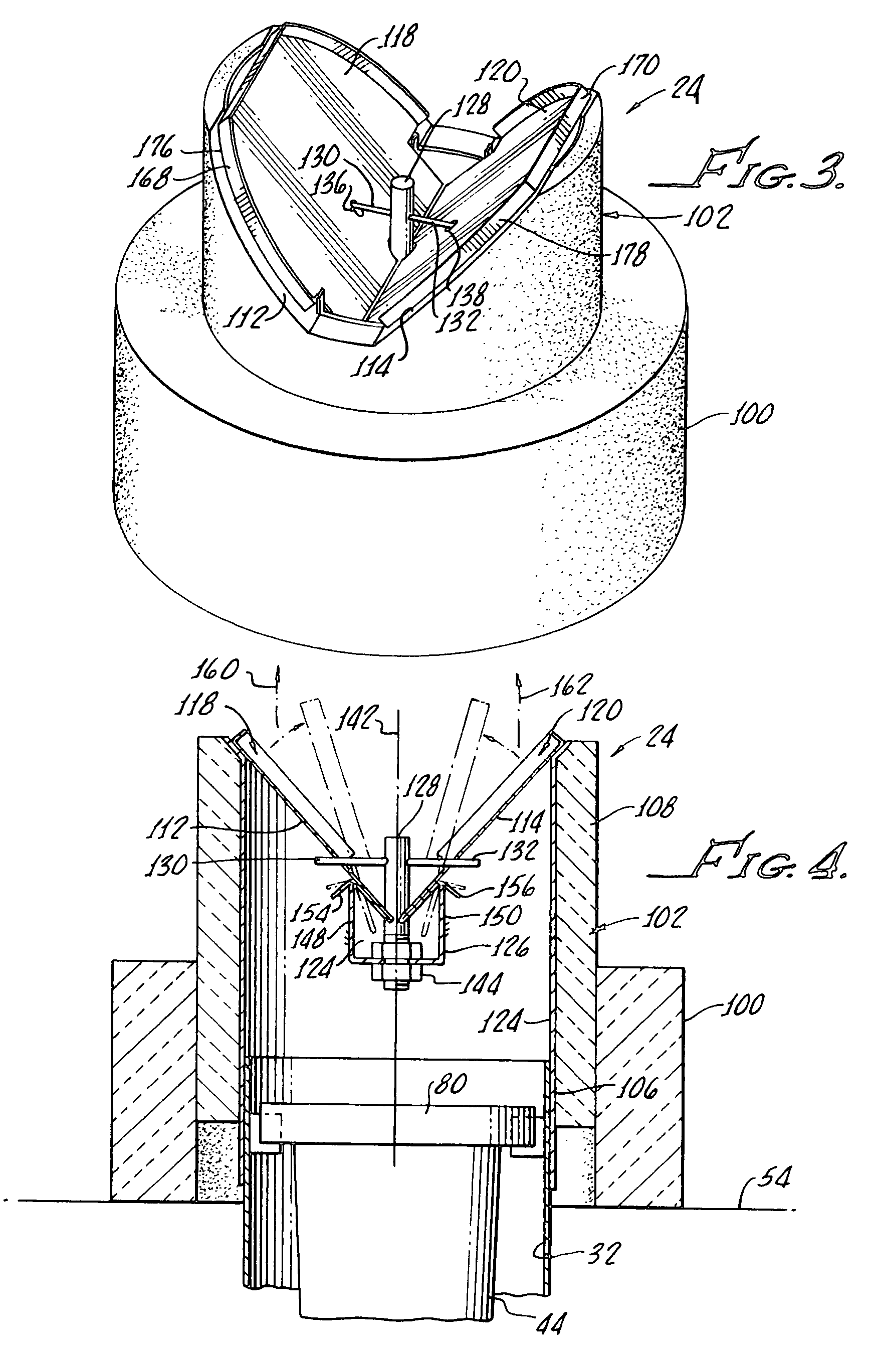
[0046]With reference to FIGS. 3 and 4, there is shown an enlarged view of the damper 24 in accordance with the present invention. A base 100 is provided and a damper assembly 102 extends from the base 100 for limitin...


PUM


Abstract

Apparatus for improving the efficiency of a water heater includes a combination damper assembly and heat transfer baffle. The damper assembly includes a plurality of movable damper with each damper leaning outwardly from one another when the dampers are in a closed position. The baffle depends from the damper assembly and includes a truncated conical shape in this position within the flue of a water heater for directing combustion gases from the burner against a flue wall.

Description

[0001]The present application is a continuation-in-part of U.S. Ser. No. 10 / 956,921 filed Oct. 2, 2004 now U.S. Pat. No. 7,000,572 and said application is incorporated herewith in its entirety herewith.[0002]The present invention generally relates to apparatus for gas burning and / or oil burning water heaters and is more particularly adapted to apparatus for improving the efficiency of a gas burning and / or oil burning water heater, hereinafter commonly referred to as a gas water heater.[0003]Typical fuel-burning water heaters include the combustion chamber disposed in a base of a water tank with a flue disposed within the tank for evacuation of the burner combustion gases therethrough and concomitant heating of water in the tank. The combustion gases exiting the water heater fluid typically pass through an exhaust flue for proper venting.[0004]U.S. Pat. No. 5,682,842 to Schimmeyer describes a segmented heat deflector including cylindrical sections for enhancing heat transfer from the...

Claims


Application Information

Patent Timeline
Patent Type & Authority Patents(United States)
IPC IPC(8): F22B7/18
CPCF22B7/18F28F13/08F24H9/0026F24H1/205
Inventor SCHIMMEYER, WERNER K.
Owner SCHIMMEYER WERNER K
Learn More