Valve apparatus

a valve and valve body technology, applied in the field of valve apparatuses, can solve the problems of unobtainable desired performance, reducing the amount of valve lift (valve opening), and reducing the time required to achieve the effect of reducing the time required to attach the valve to the body

Active Publication Date: 2007-12-25
MIKUNI CORP
View PDF4 Cites 15 Cited by
  • Summary
  • Abstract
  • Description
  • Claims
  • Application Information

AI Technical Summary

Benefits of technology

[0014]The present invention has been designed in consideration of the points described above, and it is an object thereof to provide a valve apparatus which is small and reasonably priced, and with which a flow rate can be regulated by restricting a lift amount of a valve.
[0016]According to the present invention, the valve opening restricting member comprising an opening restricting portion which does not contact the valve when the passage is closed but does contact the valve when the passage is open, is attached to the body. Thus, a valve lift amount (valve opening) can be restricted when the passage is opened by the valve, and a flow rate of liquid that flows through the passage can be maintained at a constant level. For example, in a diaphragm type pump which is activated by introduction of pulse pressure from an engine, the valve lift amount can be restricted even when the pulse pressure from the engine is excessively high, and hence an amount of fuel passing through the passage can be maintained at a constant level. Note that by preparing a plurality of washers serving as the valve opening restricting member and selecting a washer which corresponds to a desired flow rate, the desired flow rate can be obtained.
[0017]Furthermore, in the present invention, the columnar portion need only be subjected to a caulking operation in order to attach the valve and valve opening restricting member to the body, and hence time required to attach the valve to the body can be reduced. By forming the body using a synthetic resin which deforms under heat as a material, a thermal caulking operation can be performed, thereby enabling a large reduction in the time required to attach the valve to the body. The washer and valve are attached to the body by inserting the columnar portion formed on the body into the hole in the valve and the hole in the valve opening restricting member, and then crushing the columnar portion through caulking. Accordingly, an outer diameter of the columnar portion can be made smaller than an outer diameter of a neck portion of a conventional grommet, and hence an inner diameter of the hole in the valve can also be reduced. As a result, the valve itself can be reduced in size, thereby enabling a reduction in a size of the diaphragm type pump or the like comprising the valve. Moreover, since a rubber grommet does not have to be used to assemble the valve, there is no danger of deterioration caused by direct exposure to fuel.

Problems solved by technology

Due to these problems (1) through (4), it is difficult in the conventional diaphragm type pump shown in FIG. 4 to reduce a size of the pump itself, and desired performance cannot be obtained.

Method used


Image

  • Valve apparatus
  • Valve apparatus
  • Valve apparatus

Examples


Embodiment Construction

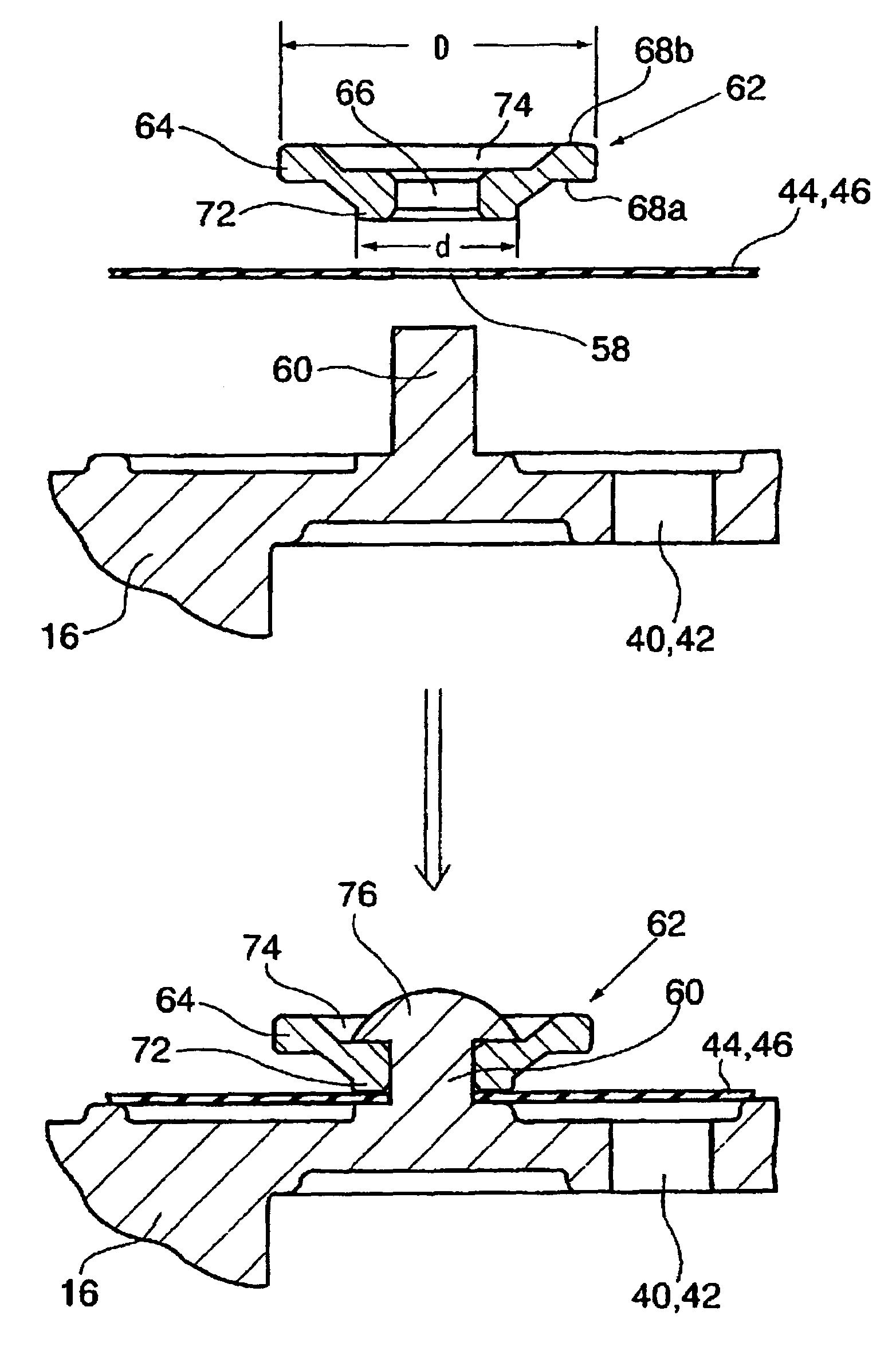
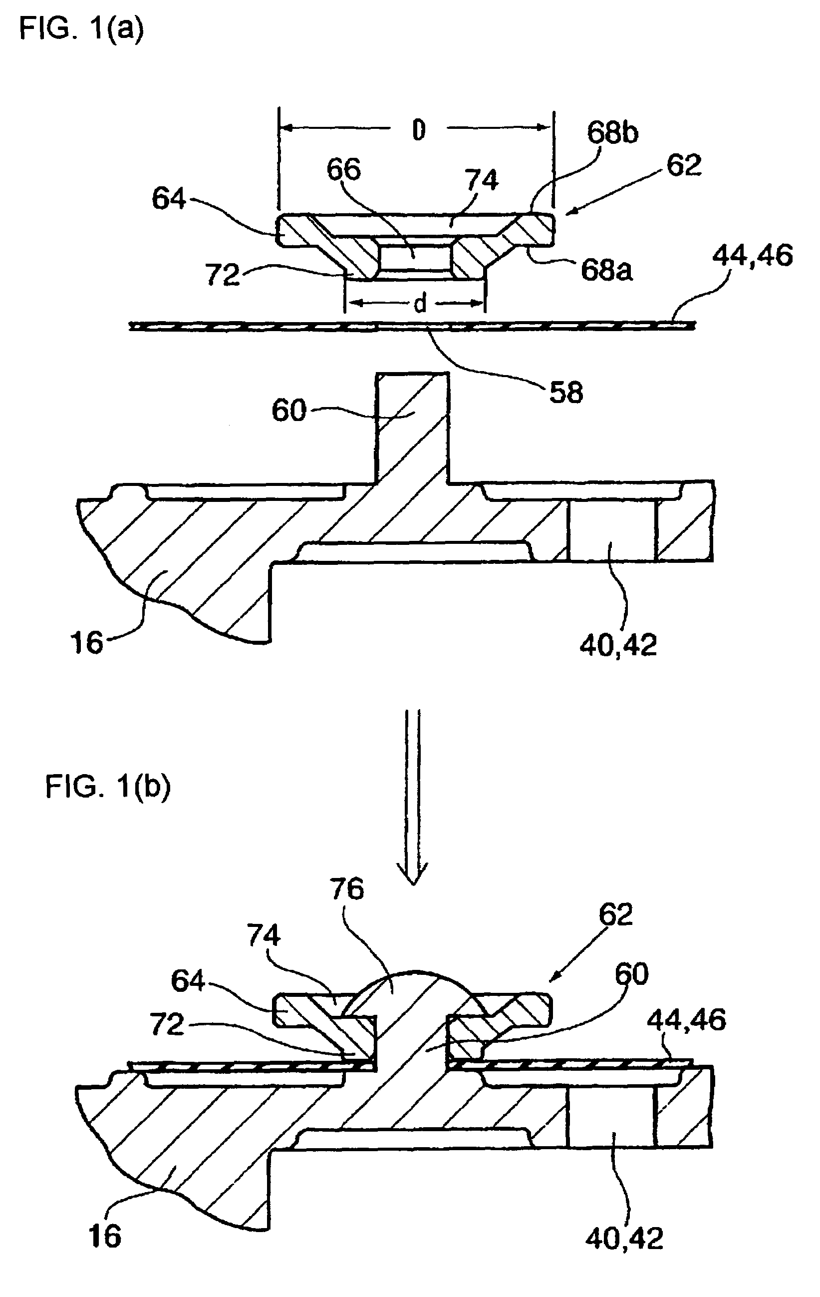
[0023]Next, the present invention will be described on the basis of the drawings. FIGS. 1(a) and 1(b) are sectional views showing a valve apparatus according to the present invention. In FIGS. 1(a) and 1(b), identical reference numerals to those used in FIGS. 4, 5(a) and 5(b) denote identical members. In place of the conventional hole 50 formed in the pump body 16 and the grommet 48 which is inserted into the hole 50, the present invention employs a columnar portion 60 formed on the pump body 16, and a washer 62 serving as a valve opening restricting member that is attached to the columnar portion 60. As shown in FIG. 1(a), the columnar portion 60 is formed integrally with the pump body (body) 16 in the vicinity of intake communication passage (passage) 40 and discharge communication passage (passage) 42. The columnar portion 60 is parallel to a passage direction of the intake communication passage 40 and discharge communication passage 42, and formed so as to protrude toward an ext...


PUM


Abstract

A valve apparatus is small, and regulates a fuel amount by restricting a lift amount of a valve. A columnar portion is formed on a pump body. The columnar portion is inserted into a check valve and a washer formed with a protruding portion which protrudes outward from a flange portion, and the check valve and washer are attached or fixed to the pump body by subjecting a tip end of the columnar portion to thermal caulking or the like. An outer diameter of the protruding portion is set to be relatively smaller than an outer diameter of the flange portion such that when the check valve is sandwiched between the protruding portion and pump body, the check valve contacts an outer peripheral edge of the flange portion when the check valve opens. As a result, a lift amount of the valve can be restricted, and a flow rate of fuel passing through a passage can be maintained at a constant level.

Description

BACKGROUND OF THE INVENTION[0001]1. Field of the Invention[0002]The present invention relates to a valve apparatus capable of regulating opening of a valve for opening and closing a passage.[0003]2. Description of Related Art[0004]Conventionally, a diaphragm type fuel pump, in which an intake / discharge pumping action is performed by activating a diaphragm using pulsation pressure of an engine, is used as a fuel supply apparatus for supplying fuel from a fuel tank to a fuel injection apparatus or the like. Japanese Unexamined Patent Application 2002-202026 is known as an example of a conventional diaphragm type fuel pump, structure of which is shown in FIGS. 3 and 4. A fuel pump 10 is constituted by a pump body 16 formed with an intake port 12 and a discharge port 14, shown in FIG. 3, a bottom body 18 disposed on one of side faces of the pump body 16, a cover 20 disposed on another side face of the pump body 16, a diaphragm 22 sandwiched between the pump body 16 and bottom body 18, a...

Claims


Application Information

Patent Timeline
Patent Type & Authority Patents(United States)
IPC IPC(8): F16K15/14
CPCF04B53/105F16K15/144F04B53/1062Y10T137/6086Y10T137/784Y10T137/789Y10T137/7892
Inventor TAKEHANA, NORIOCHIBA, NORIAKIIMAMATSU, HIDEKI
Owner MIKUNI CORP
Why Eureka
Try Eureka