Pneumatic tool with direction switch operable with single hand

a pneumatic tool and single-hand technology, applied in the field of pneumatic tools, can solve the problems of user injury to the hand, inability to hold the pneumatic tool b>1/b> steady with the middle finger, the ring finger, etc., and achieve the effect of simple structur

Inactive Publication Date: 2007-12-25
PNEUTECH MFG
View PDF6 Cites 41 Cited by
  • Summary
  • Abstract
  • Description
  • Claims
  • Application Information

AI Technical Summary

Benefits of technology

[0010]The primary advantage of the pneumatic tool according to the present invention is the simple structure for the use of the simple controller including only the first and second grooves.

Problems solved by technology

However, there are problems with this conventional pneumatic tool 1.
The user might get hurt in the hand if using this pneumatic tool 1 for long.
Moreover, the user cannot hold the pneumatic tool 1 steady with the middle finger, the ring finger and the little finger.
Furthermore, the user may unintentionally press the upper control member 3 with the index finger and change the direction of the rotation of the pneumatic tool 1, and this could be dangerous.
However, there are problems with this conventional direction switch.
The user soon has fatigue in the hand.
The user might get hurt in the hand if using this pneumatic tool for long.
Moreover, the user cannot hold the pneumatic tool steady with the middle finger, the ring finger and the little finger.
In addition, the user may unintentionally change the direction of the rotation of the pneumatic tool, and this could dangerous.
Furthermore, the elements are numerous, and the direction switch is complicated.
The assembly, the maintenance and the repair of the direction switch are difficult.

Method used


Image

  • Pneumatic tool with direction switch operable with single hand
  • Pneumatic tool with direction switch operable with single hand
  • Pneumatic tool with direction switch operable with single hand

Examples


Embodiment Construction

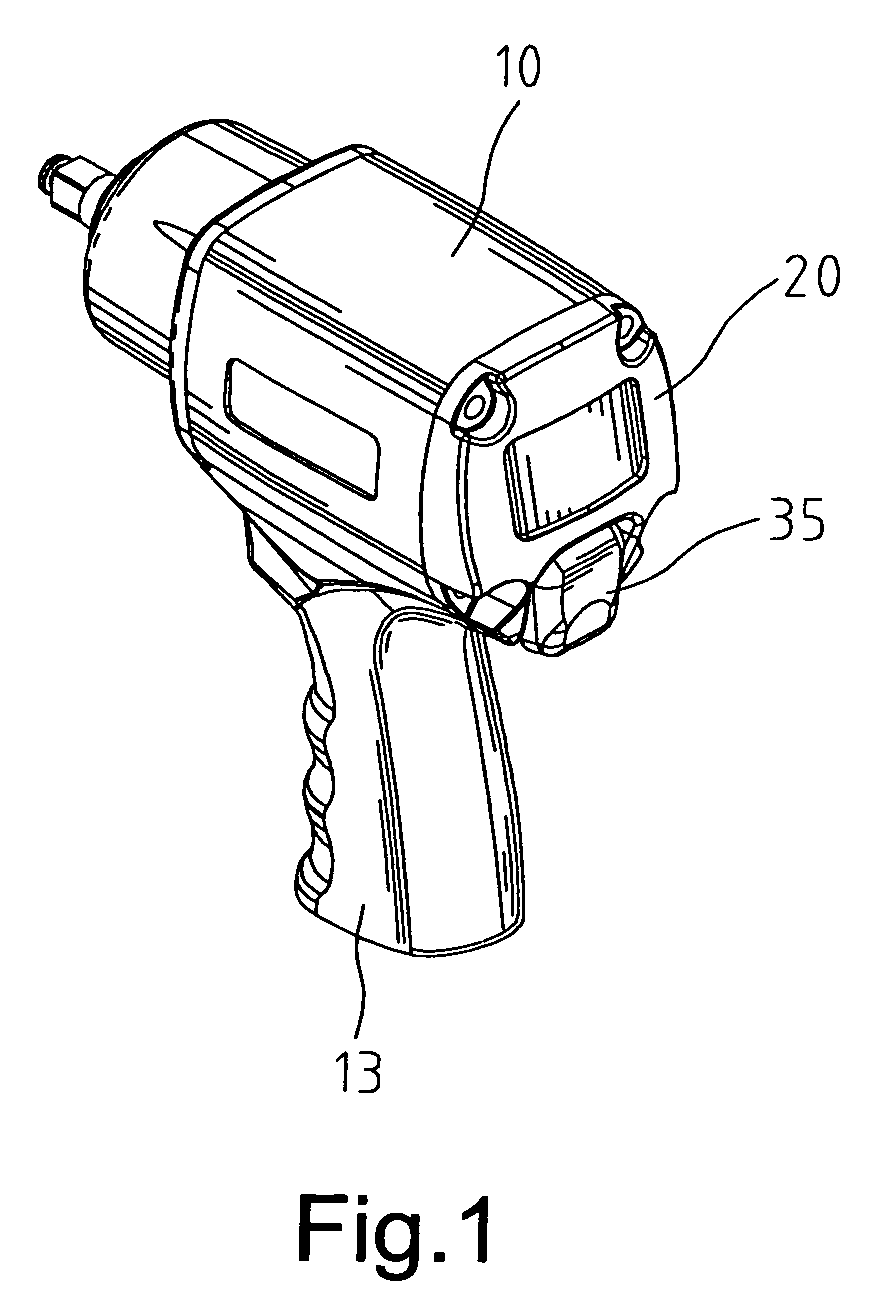
[0020]Referring to FIG. 1, shown is a pneumatic tool according to the preferred embodiment of the present invention.

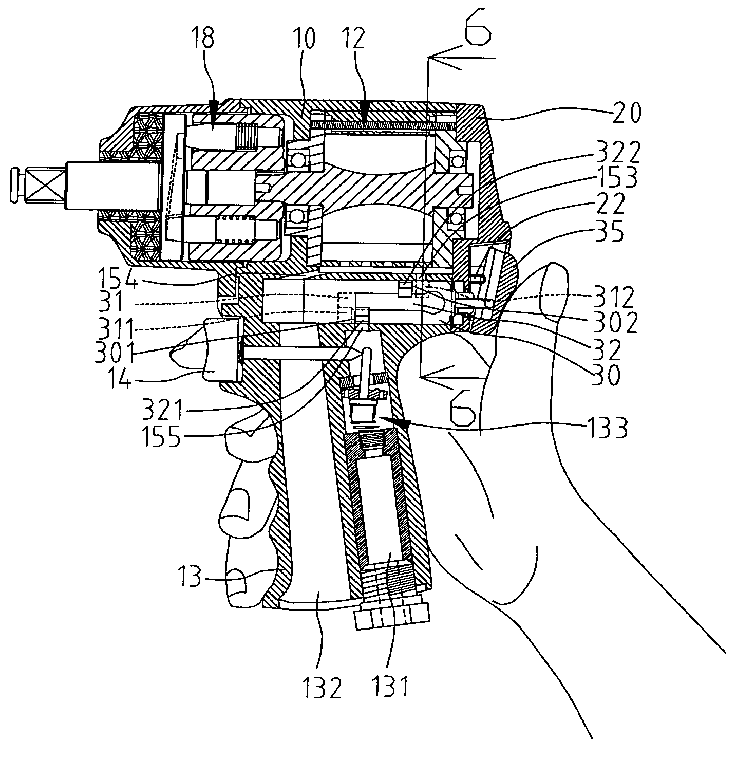
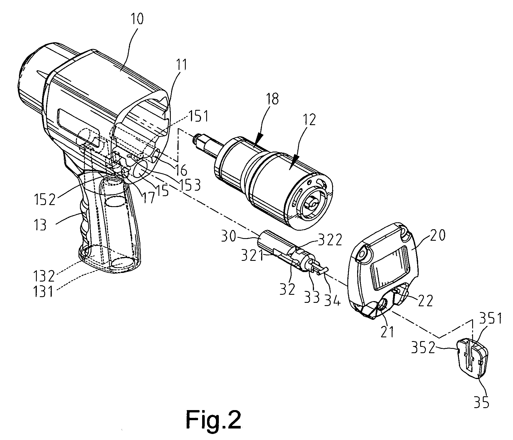
[0021]Referring to FIGS. 2 through 4, the pneumatic tool includes a shell 10 and a handle 13 projecting from the shell 10. The shell 10 defines a first chamber 11, a second chamber 15, a first channel 16 and a second channel 17. The first chamber 11 receives a cylinder 12 for driving a striker 18. The second chamber 15 receives a controller 30.

[0022]The handle 13 defines an intake 131 and an outlet 132. The intake 131 receives a valve 133 movable by a trigger 14 installed on the handle 13.

[0023]The second chamber 15 is in communication with the first channel 16 through an aperture 151 on a side. The second chamber 15 is in communication with the second channel 17 through an aperture 152 on another side. The second chamber 15 is in communication with the first chamber 11 through an intake aperture 153 near an end. Moreover, the second chamber 15 is in communication with...


PUM

PropertyMeasurementUnit
diameteraaaaaaaaaa
air currentsaaaaaaaaaa
distanceaaaaaaaaaa

Abstract

A pneumatic tool is operable with a single hand. The pneumatic tool includes a shell defining a first chamber and a second chamber. The second chamber includes intake and outlet apertures in communication with the first chamber. A cylinder is in the first chamber. A controller is movable in the second chamber between a first position and a second position. The controller includes a first groove and a second groove. In the first position, the first groove communicates with the intake aperture for directing pressurized air to drive the cylinder in a first direction. In the second position, the second groove communicates with the intake aperture for directing pressurized air to drive the cylinder in a second direction. A cover seals the first chamber and the second chamber. The cover defines an opening through which the controller extends from the second chamber so that the controller can be moved.

Description

BACKGROUND OF INVENTION[0001]1. Field of Invention[0002]The present invention relates to a pneumatic tool and, more particularly, to a pneumatic tool equipped with a direction switch operable with a single hand.[0003]2. Related Prior Art[0004]Disclosed in Taiwanese Patent Publication No. 387316 is a pneumatic tool 1 equipped with a direction switch operable with a single hand. The pneumatic tool 1 includes a handle 11 on which an upper control member 2 and a lower control member 3 are installed. The upper control member 2 is operable to cause the pneumatic tool 1 to rotateor stop. The lower control member 3 is operable to cause the pneumatic tool 1 to rotate in a direction or in an opposite direction. A user operates the pneumatic tool 1 with a single hand. The user holds the handle 11 and the lower control member 2 with the thumb, the middle finger, the ring finger and the little finger. The user presses the lower control member 2 with the middle finger, the ring finger and the lit...

Claims


Application Information

Patent Timeline
Patent Type & Authority Patents(United States)
IPC IPC(8): B23B45/04
CPCB25F5/00
Inventor CHANG, JUI-SHENG
Owner PNEUTECH MFG
Why Eureka
Try Eureka