

Adjustable beam lamp
a beam lamp and adjustable technology, applied in the field of reading lamps, can solve the problems of easy burnout of the bulbs of the lamps, and achieve the effects of long lamp life, easy operation, and cool operating temperatures
- Summary
- Abstract
- Description
- Claims
- Application Information
AI Technical Summary
Benefits of technology
Problems solved by technology
Method used
Image

Examples
Embodiment Construction
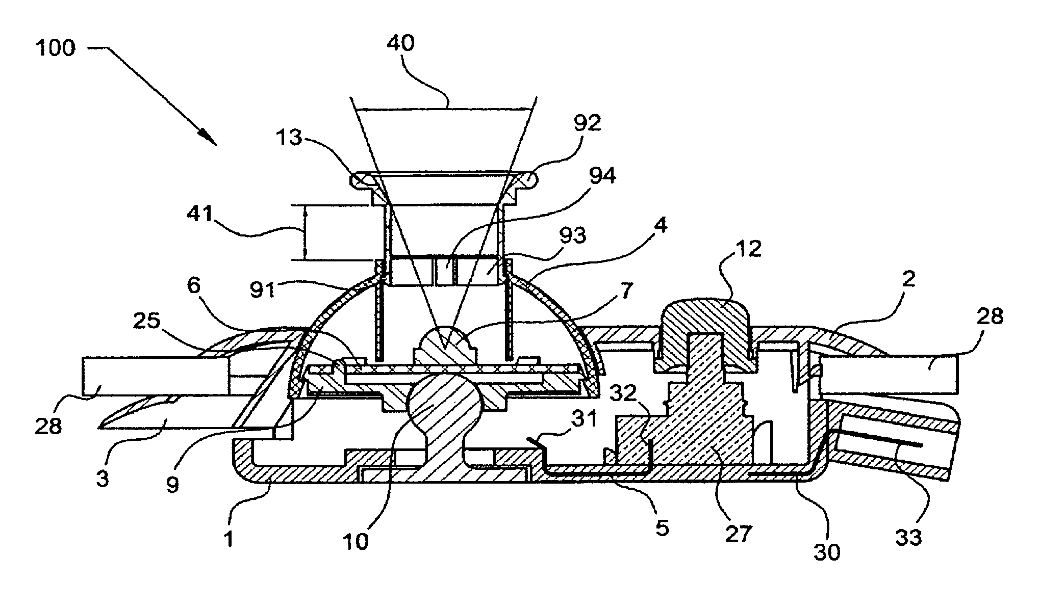
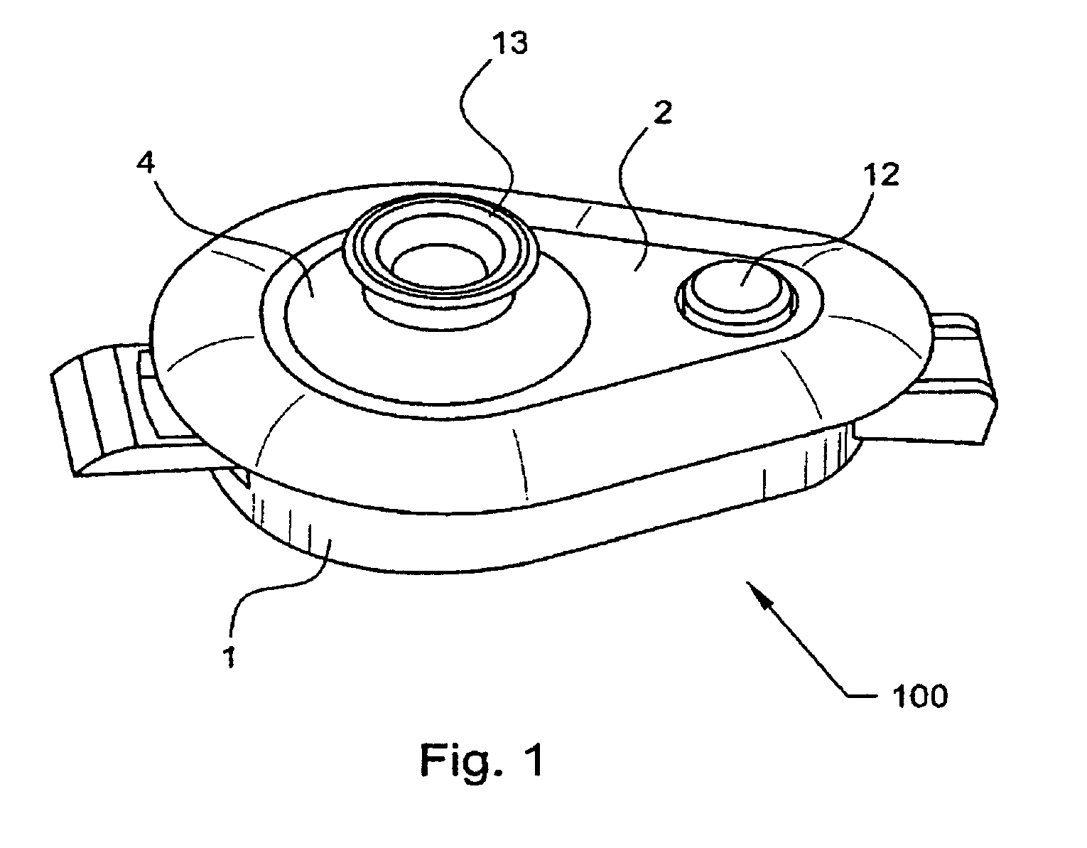
[0032]Reference will now be made to the drawings, wherein to the extent possible like reference numerals are utilized to designate like components throughout the various views. Referring to FIG. 1, which presents a perspective front view of a preferred embodiment of the adjustable beam lamp 100 of the present invention having a lamp housing 1 with mounting bracket 5, bezel 2 with mounting bracket 3, dome shaped eyeball housing 4, light tube 13, and push / push button cover 12.
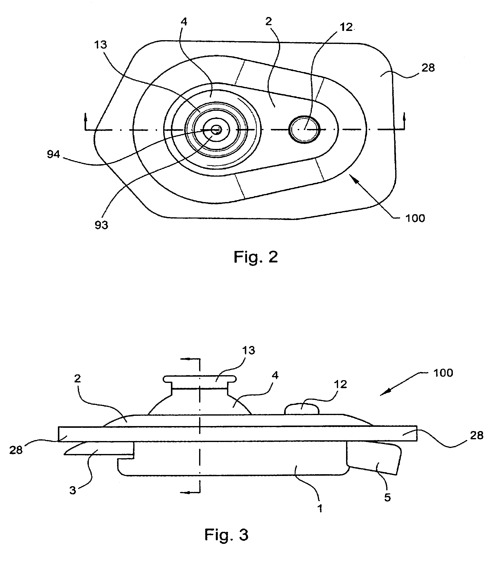
[0033]Referring now to FIG. 2, there is shown a plan front view of the adjustable beam lamp 100 showing the mounting bracket 5 of lamp housing 1, the bezel 2 with mounting bracket 3, dome shaped eyeball housing 4, push / push button cover 12, and the light tube 13 with mid wall 93 and light clipping bore 94 located therein.
[0034]Turning now to FIG. 3, there is shown the adjustable beam lamp 100 in a plan side view showing lamp housing 1 with mounting bracket 5, bezel 2 with bezel mounting bracket 3, dome shaped eye...
PUM
 Abstract
Description
Claims
Application Information