Distribution of a flowing medium

a technology of flowing medium and spreading medium, which is applied in the direction of papermaking, textiles and paper, coatings, etc., can solve the problems of increasing the difficulty of uniform distribution of fibrous suspension, increasing poor efficiency, so as to reduce the risk of plugging, the effect of shortening the length and shortening the transport distan

Inactive Publication Date: 2007-12-25
VALMET TECH INC
View PDF6 Cites 2 Cited by
  • Summary
  • Abstract
  • Description
  • Claims
  • Application Information

AI Technical Summary

Benefits of technology

[0025]In this manner the head box can be abolished, which implies several further advantages. A roll press of conventional type comprises two rotary rolls, which between them form a nip for dewatering the suspension. The rolls are mounted in a trough. In order not to block the way when there is need to have access to the press from above, the head box was normally placed outside the trough, and the distribution housing was supplied with suspension from below and outside the trough. The trough has a certain extension, as seen radially, outwardly from the rolls. As a result, the distribution unit must comprise a transport channel for transport of the suspension from the outlet opening to the surface where the pulp web shall be formed (the rolls). The longer this transport channel is, the greater becomes the plugging risk.
[0026]According to the present invention, the distribution housing is fed from above. The pipes, through which the suspension is supplied, do not hinder access to the press, if such access is required. The transport channel of the distribution unit can thereby be given a shorter length whereby the transport distances become shorter and the plugging risk is thus reduced.

Problems solved by technology

The difficulty of distributing the fibrous suspension uniformly, across the entire width increases rapidly with increasing pulp concentration as a consequence of the increasing shearing strength of the fiber network.
Non-uniform distribution of the fibrous suspension not only results in non-uniform dewatering and thereby poor efficiency of the liquid treatment, it can also cause in a press damages on the fibers and, thus, deteriorated pulp quality.
In the roll nip between the rolls, for example in a roll press, fiber flocks and thick portions of the pulp web can be subjected to compacting pressures so high that the fibers are damaged in these load-carrying portions.
With such a device of a known type, problems arise in that the pulp web becomes non-uniform as seen along the entire width of the web.
Problems also arise because the distribution units at times can plug.
It has thus been found that the head box at times does not deliver the same flow in all outlets.
Particularly during low flows the pressure drop created in the throttlings becomes too low for providing a good distribution.
This, in turn, results in the different distribution units not being fed fully equally which, of course, results in a non-uniform web.
It is also due to the non-uniform distribution from the head box to the distribution units that the distribution units can plug.

Method used


Image

  • Distribution of a flowing medium

Examples


Embodiment Construction

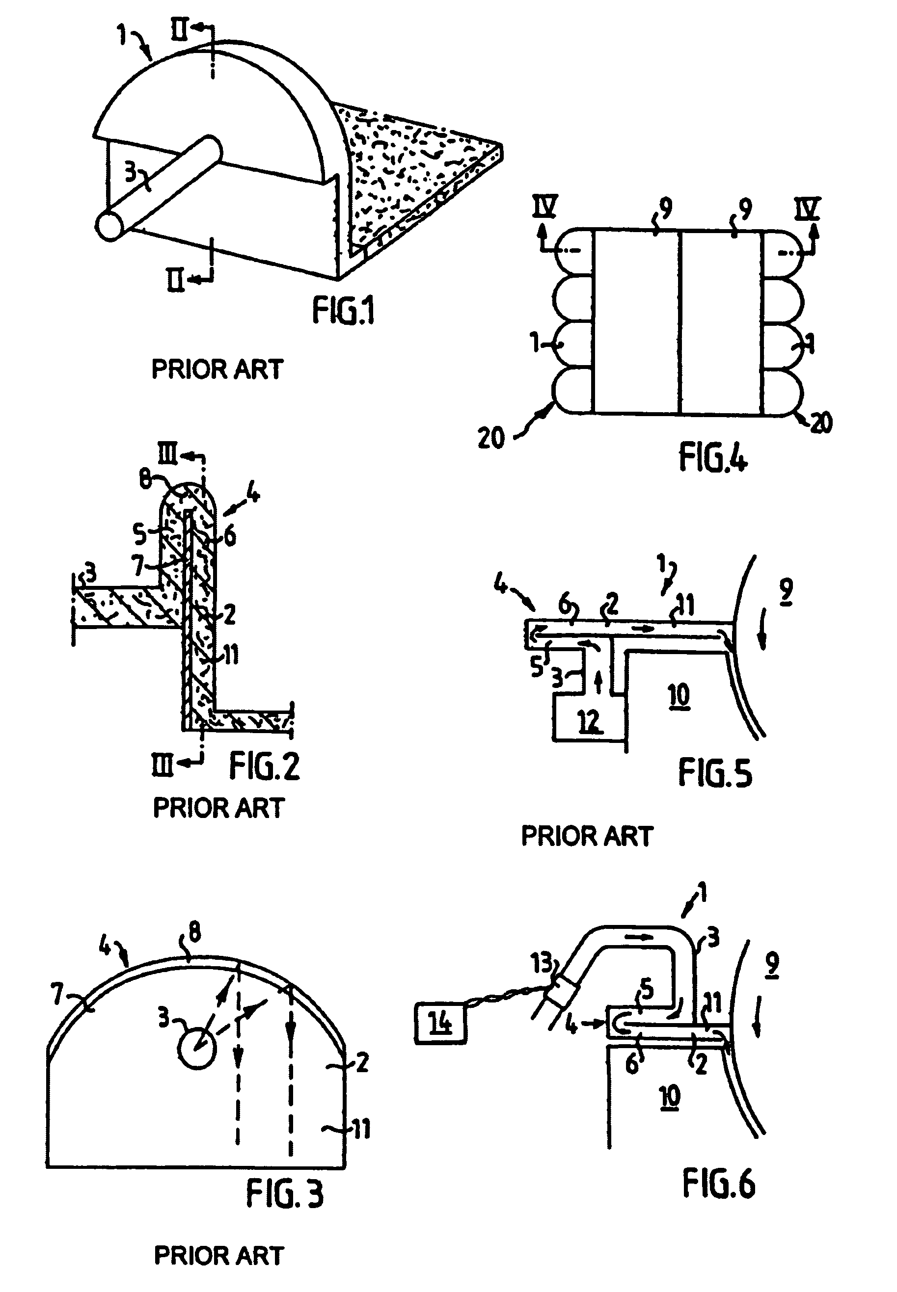
[0035]FIGS. 1, 2 and 3 show a distribution unit 1 of the type described in Swedish patent specification No. 500,546. The distribution unit 1 is intended for transverse distribution and forming a web of a flowing medium, for example a pulp web of a fibrous suspension. The distribution unit will be described only roughly, because it is known per se. The distribution unit 1 comprises a distribution housing 4 with a wide substantially rectangular outlet opening 2 and a supply pipe 3 for the fibrous suspension.

[0036]The outlet opening 2 transforms to a transport channel 11, which has a width equal to the outlet opening 2 and is intended to transport the suspension from the outlet opening 2 to the place where the pulp web shall be formed.

[0037]The distribution housing 4 is formed with a distribution chamber 5, which is located substantially transversally to the supply pipe 3 and extends from the connection of this pipe 3 diverging in the direction to a passage 8 bent in the transverse dir...


PUM


Abstract

Methods for uniformly distributing a flowing medium to a surface such as that of a rotary liquid permeable roll are disclosed where the flowing medium is distributed by a number of distribution units, the method including distributing the flowing medium to each of the distribution units and separately controlling the flow of the flowing medium to each of the distribution units whereby a uniform flow and an equal amount of the flowing medium is obtained in each of the distribution units. Distribution devices for uniformly distributing a flowing medium to such a surface are also disclosed.

Description

[0001]This application is a 371 of PCT / SE02 / 01286 filed 28 Jun. 2002.FIELD OF THE INVENTION[0002]The present invention relates to a method and a device for the uniform spreading and distribution of a flowing medium, for example a pulp suspension, where the medium is distributed by at least two distribution units.BACKGROUND OF THE INVENTION[0003]As an example, the present invention can be applied to the field of cellulose, and the need of the papermaking industry to form webs of fibrous suspensions, which are often more than 10 meters wide and have very high requirements for uniformity both across and along the manufacturing direction. The uniformity of the webs is often totally decisive for the efficiency and economy of the process.[0004]During, for example, liquid treatment, i.e. washing or bleaching and dewatering of fibrous suspensions, it is essential that the pulp is applied to and distributed transversely on a continuous liquid permeable support as uniformly as possible, both ...

Claims


Application Information

Patent Timeline
Patent Type & Authority Patents(United States)
IPC IPC(8): D21F1/00D21F1/02
CPCD21F1/028D21F1/02
Inventor DANIELSSON, MAGNUSLUNDBERG, JORGEN T.
Owner VALMET TECH INC
Why Eureka
Try Eureka