Device for fastening elongate elements to a structure

a technology of elongate elements and devices, applied in the direction of capacitors, pipe supports, electrical devices, etc., to achieve the effect of simplifying installation plans

a technology of elongate elements and devices, applied in the direction of capacitors, pipe supports, electrical devices, etc., to achieve the effect of simplifying installation plans

US7312399B2Inactive Publication Date: 2007-12-25EUROCOPTER

Image

  • Device for fastening elongate elements to a structure
  • Device for fastening elongate elements to a structure
  • Device for fastening elongate elements to a structure

Examples


first embodiment

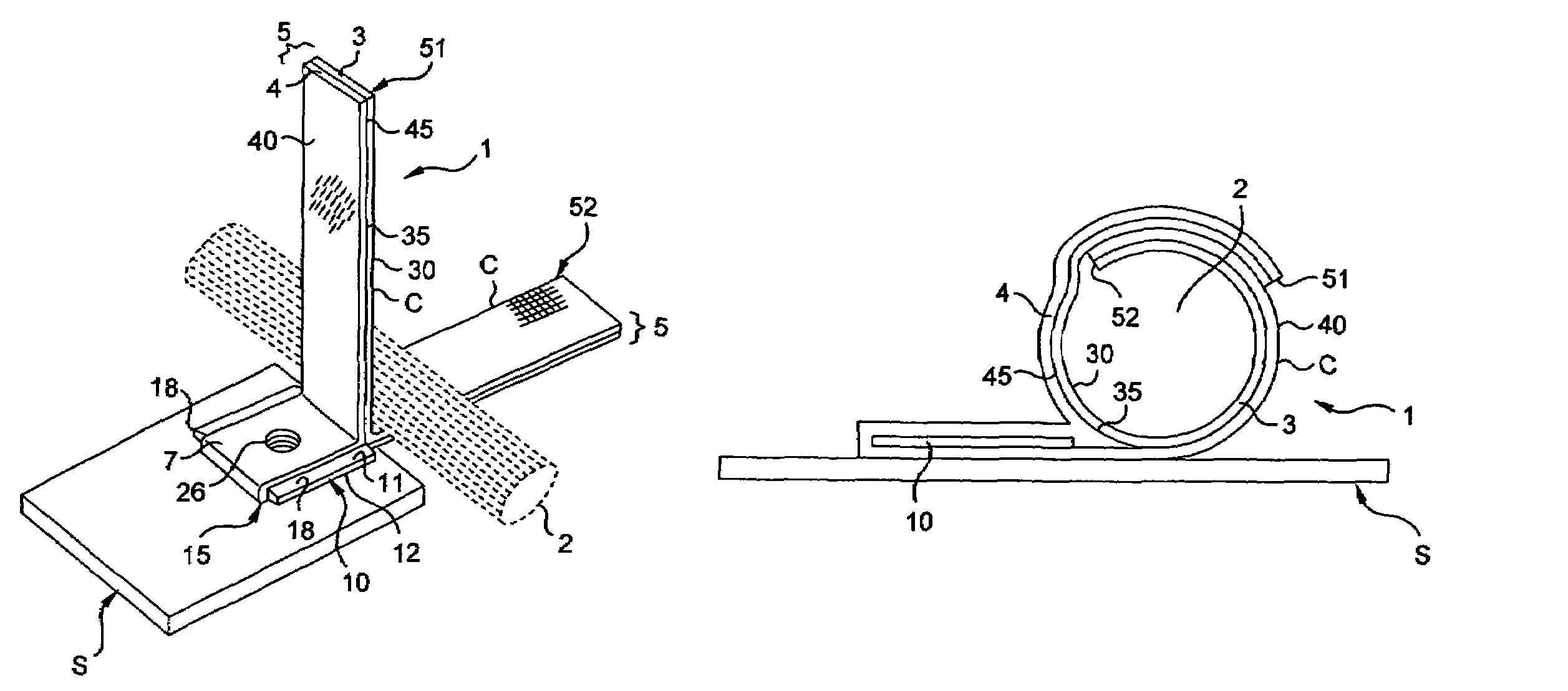
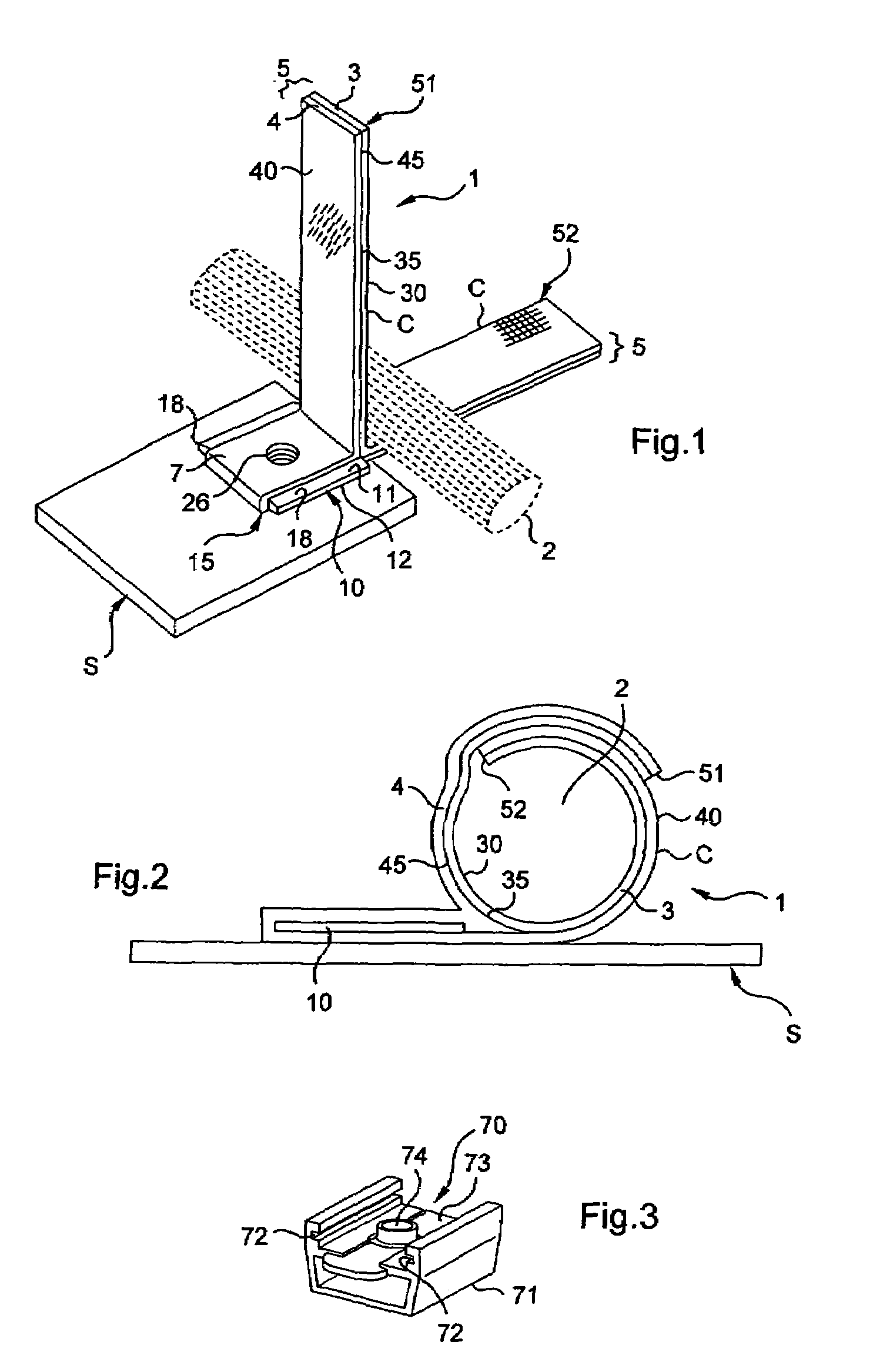
[0059]The device 1 for fastening elongate elements as shown in FIG. 1 corresponds to the invention and comprises a first flexible self-gripping strip 3 with a loop-closure system on a first face 30, and a second flexible self-gripping strip 4 with a hook-closure system on a first face 40, each of these first and second flexible strips having a respective second face 35 or 45 that is self-adhesive, and both of them being identical in width. By way of example, each of them may be a Velcro™ type strip, either having a hook-closure system (a “male” system) or a loop-closure system (a “female” system).

[0060]Said first and second flexible strips 3 and 4 adhere at least in part one against the other via their self-adhesive second faces 35 and 45 so as to form a first flexible tape 5 by uniting together at least the facing first and second free end zones 51 and 52 of said first and second flexible strips 3 and 4.

[0061]The length of the flexible tape 5 is longer than the outer perimeter of t...

second embodiment

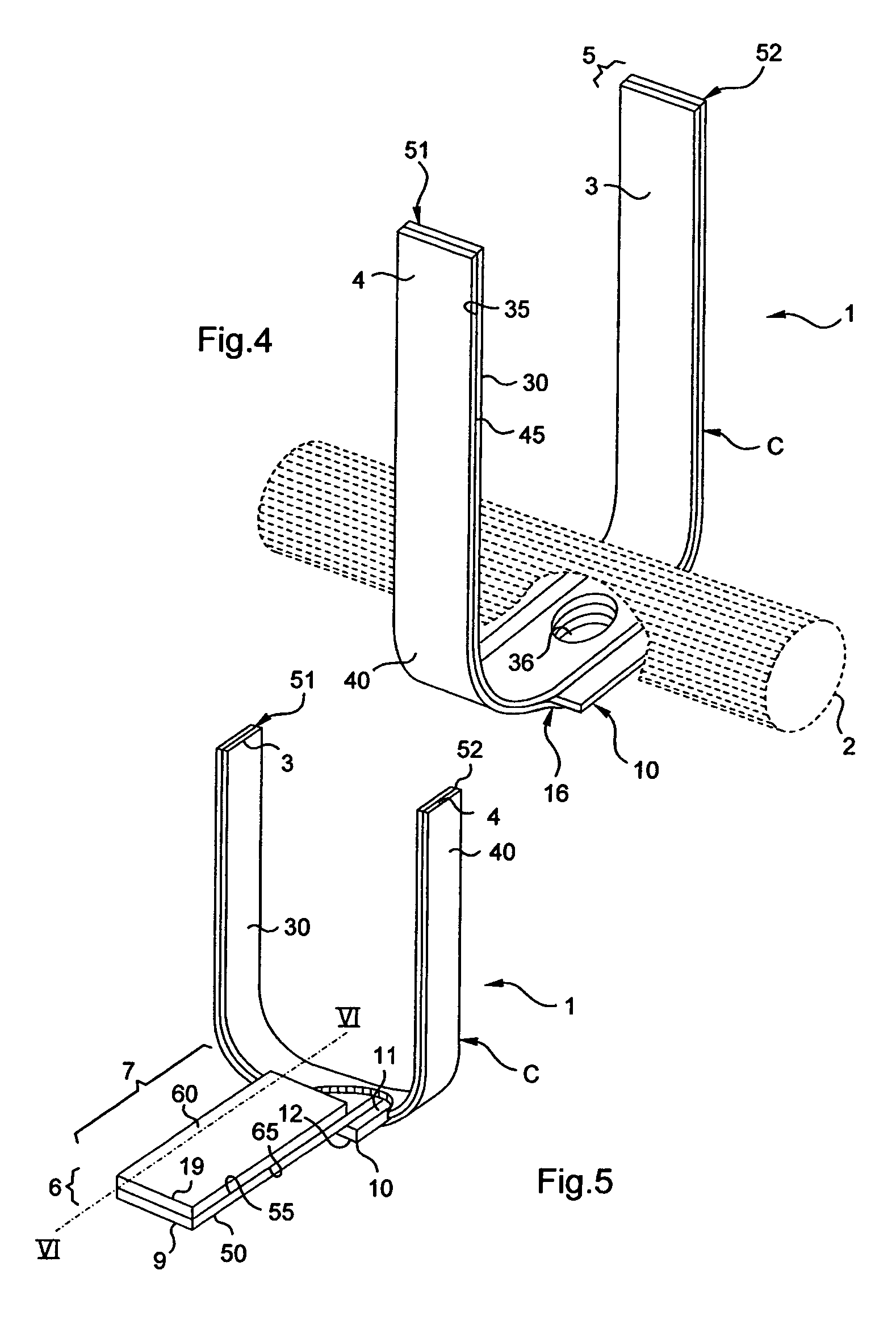
[0068]In a second embodiment shown in FIG. 4, the flexible strips 3 and 4 are identical in length and said rigid plate 10 is inserted with adhesive between said flexible strips 3 and 4, being substantially centered between the free ends 51 and 52 so as to constitute a non-offset fastening support 16 for fastening to said structure S (not shown in FIG. 4), without said device 1 being offset.

[0069]Thus, a collar C is obtained by adhesion between the face 30 of the free end 51 on the face 40 of the free end 52, or of the face 40 of the free end 51 on the face 30 of the free end 52.

[0070]At the level of the non-offset fastening support 16 shown in FIG. 4, the flexible strips 3 and 4 and also the rigid plate 10 presents a hole 36 for securing said flexible collar C to said structure S by clamping means engaged in said hole 36.

[0071]In a variant, the rigid plate 10 may naturally present a projection 18 on either side of the flexible tape 5 in the same manner as in the first embodiment, th...


PUM

PropertyMeasurementUnit
flexibleaaaaaaaaaa
lengthaaaaaaaaaa
widthaaaaaaaaaa

Abstract

A device (1) for fastening elongate elements (2) such as cables or bundles of cables or the like to a structure (S) includes at least a first flexible self-gripping strip (3) having a loop-closure system on a first face (30) and a second flexible selfgripping strip (4) with a hookclosure system on a first face (40) The first and second flexible strips (3 and 4) adhere at least in par.t one against the other via their second faces (35 and 45) that are self-adhesive, so as to form a flexible collar (C) by uniting at least their facing free end zones (51 and 52) The device further includes a rigid plate (10) for constituting a support for fastening the device (1) to the structure (S).

Description

BACKGROUND OF THE INVENTION[0001]The present invention relates to a device for fastening elongate elements such as cables or bundles of electrical cables, optical cables, or other cables, ducts or pipework for fluids or the like, the device enabling said elongate elements to be held and guided relative to a support structure.[0002]More generally, the invention relates in particular to manufacturing vehicles, in the automotive industry, in ship building, and more particularly in the aircraft industry. An aircraft includes a multiplicity of pieces of equipment and various apparatuses that for control purposes, require very many circuits of all types (electrical, optical, fluid conveying, . . . ) for transmitting information essential to proper operation of the vehicle as a whole. Consequently, it is important to secure these multiple circuits and to guide them appropriately relative to the structure of said aircraft.[0003]Naturally, the device is not limited to this particular applica...

Claims


Application Information

Patent Timeline
25 Dec 2007
Publication
US7312399B2
IPC
H01B7/00
CPC
F16L3/1025; H02G3/32; F16L3/137
Inventors
GIROT, GAEL