Systems and methods for inspecting electrical conductivity in composite materials

a composite material and electrical conductivity technology, applied in the direction of resistance/reactance/impedence, material magnetic variables, instruments, etc., can solve the problems of prone to error, difficult surface conductivity measurement methods, and relative poor electrical conductivity of fiber-reinforced composite skin panels

Active Publication Date: 2007-12-25
THE BOEING CO
View PDF17 Cites 25 Cited by
  • Summary
  • Abstract
  • Description
  • Claims
  • Application Information

AI Technical Summary

Problems solved by technology

Increasingly, however, structural portions (including skin panel portions) of commercial airplanes are formed from fiber-reinforced composite materials, which are relatively poor electrical conductors.
Similarly, fiber-reinforced composite skin panels may also require a localized repair to remove a portion of the panel that has been physically damaged.
Accordingly, surface conductivity measurement methods are tedious and are prone to error if not performed correctly.

Method used


Image

  • Systems and methods for inspecting electrical conductivity in composite materials
  • Systems and methods for inspecting electrical conductivity in composite materials
  • Systems and methods for inspecting electrical conductivity in composite materials

Examples


Embodiment Construction

[0016]The present invention relates to systems and methods for inspecting electrical conductivity in composite materials, and in particular, to the inspection of electrical conductivity in electrical bonding regions. Many specific details of certain embodiments of the invention are set forth in the following description and in FIGS. 1 through 7 to provide a thorough understanding of such embodiments. One skilled in the art, however, will understand that the present invention may have additional embodiments, or that the present invention may be practiced without several of the details described in the following description.

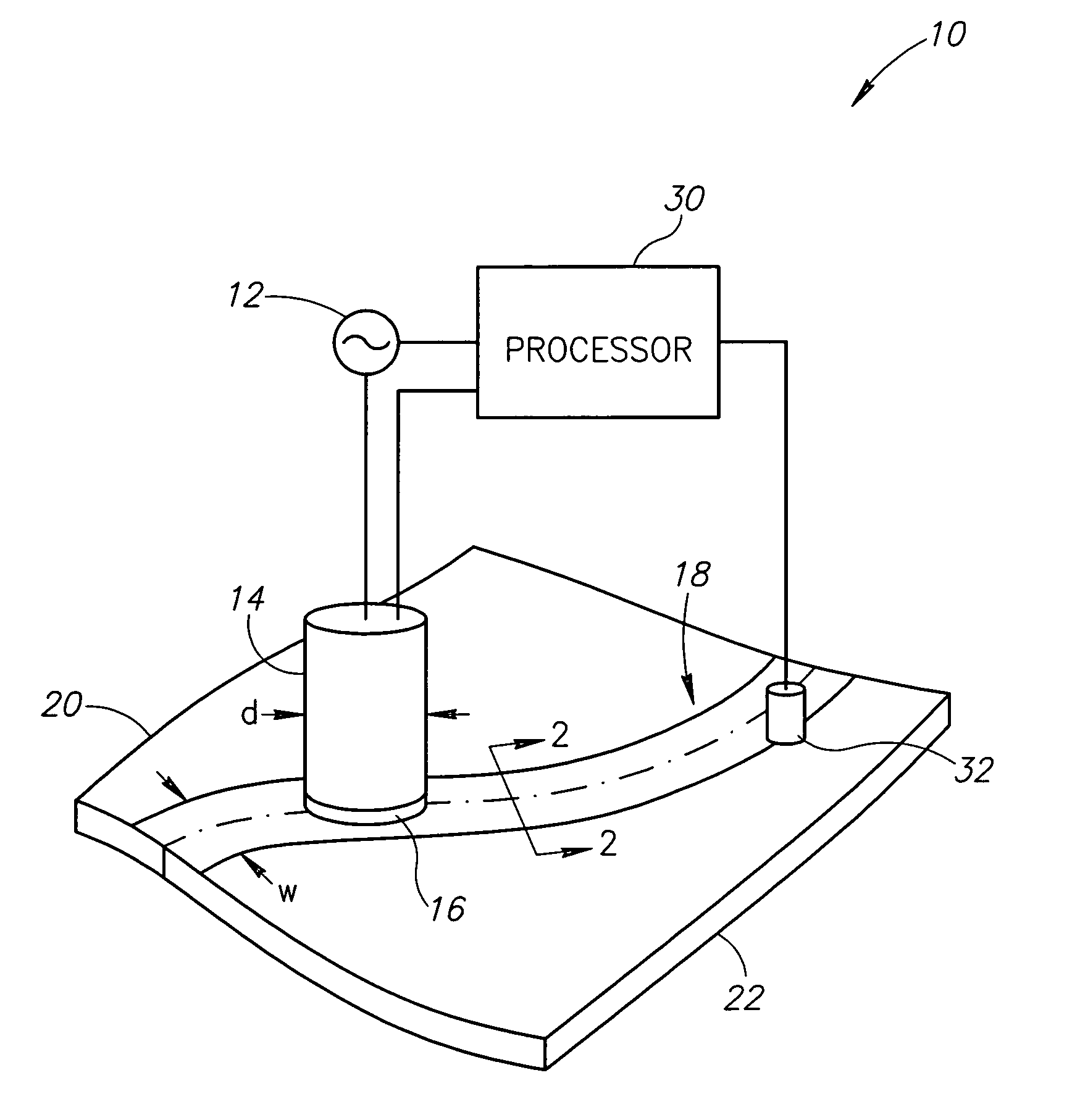
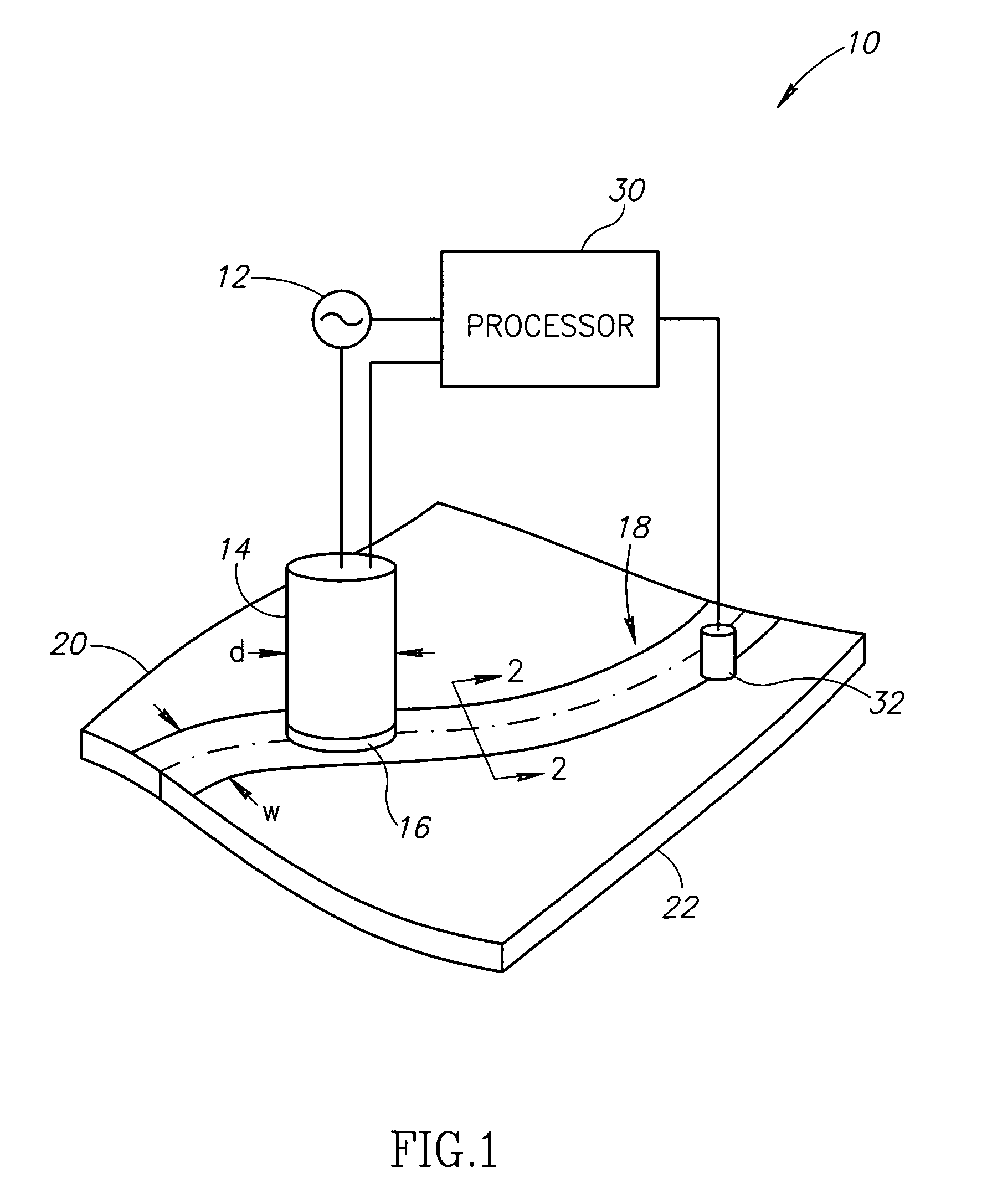
[0017]FIG. 1 is a partial schematic view of a system 10 for inspecting an electrical bonding region, according to an embodiment of the invention. The system 10 includes an alternating current source 12 that is configured to generate an alternating current having a desired frequency. In one specific embodiment, the source 12 is configured to generate the alternating...


PUM

PropertyMeasurementUnit
frequencyaaaaaaaaaa
frequencyaaaaaaaaaa
frequencyaaaaaaaaaa

Abstract

Systems and methods for inspecting electrical conductivity in composite materials having conductive structures are disclosed. In one embodiment, a system of inspecting electrical conductivity in an electrical bonding region includes a coil coupled to an alternating current source that is configured to induce a current in a conductive structure within the region. A processor is coupled to the coil that is operable to detect an impedance property value from the coil that results from the current induced in the conductive structure.

Description

FIELD OF THE INVENTION[0001]This invention relates generally to systems and methods for inspecting composite materials having a conductive structure, and more specifically, to systems and methods for inspecting an electrical bonding region that couples adjoining composite materials.BACKGROUND OF THE INVENTION[0002]Recent estimations indicate that, on the average, each airplane in the U.S. commercial aircraft fleet receives a lightning discharge about once each year. The airplane generally experiences the lightning discharge when flying through a heavily charged portion of a cloud. In such cases, the discharge generally originates at the airplane and extends outwardly from the aircraft. While the discharge is occurring, it generally moves from the nose of the airplane and onto a plurality of skin panel portions of the airplane as it moves through the charged region. The discharge may also attach to wing tips and / or edges of wing control surfaces (e.g., ailerons) during the discharge....

Claims


Application Information

Patent Timeline
Patent Type & Authority Patents(United States)
IPC IPC(8): G01N27/82G01R31/08
CPCG01R27/2623G01N27/9046G01N33/442
Inventor GEORGESON, GARY E.HAFENRICHTER, JOSEPH L.WESTERMAN, EVERETT A.
Owner THE BOEING CO
Why Eureka
Try Eureka