
Illuminated wearable ornament

a wearable ornament and illumination technology, applied in the field of electronic ornaments, can solve the problems of not being able to recognize the trade-off between readability and prior art, not being able to create personal messages, graphic, or animated images, etc., and achieve the effects of reducing the frequency of battery change, and reducing the size of the battery

Inactive Publication Date: 2007-12-25
RAPID PROTOTYPES
View PDF19 Cites 30 Cited by
  • Summary
  • Abstract
  • Description
  • Claims
  • Application Information

AI Technical Summary

Benefits of technology

[0021]Further, the inventive system includes a control circuit capable of causing the array to display alphanumeric characters, symbols, graphics, or animated images. User programming is enabled in a preferred embodiment with two pushbutton switches and a programming connector. The user (1) pushes two buttons simultaneously to select a character for editing purposes as the character scrolls across the display, (2) double-clicks a button to step to the next character in a message, and (3) presses two buttons simultaneously to switch between alternative character sets when editing a character. These controls allow a broad range of functionality while keeping the number of buttons, and hence cost, to a minimum.

Problems solved by technology

These are not suitable for use as jewelry, ornaments, or items of apparel, because they are too large and heavy, would not operate for long enough on a small enough battery, or are too expensive to manufacture.
Some provide a choice between a few different sequences of flashing pulses, but none allow a user to create a personal message, graphic, or animated image.
The prior art does not recognize the tradeoff between readability and economy of a scrolling display.

Method used


Image

  • Illuminated wearable ornament
  • Illuminated wearable ornament
  • Illuminated wearable ornament

Examples


Embodiment Construction

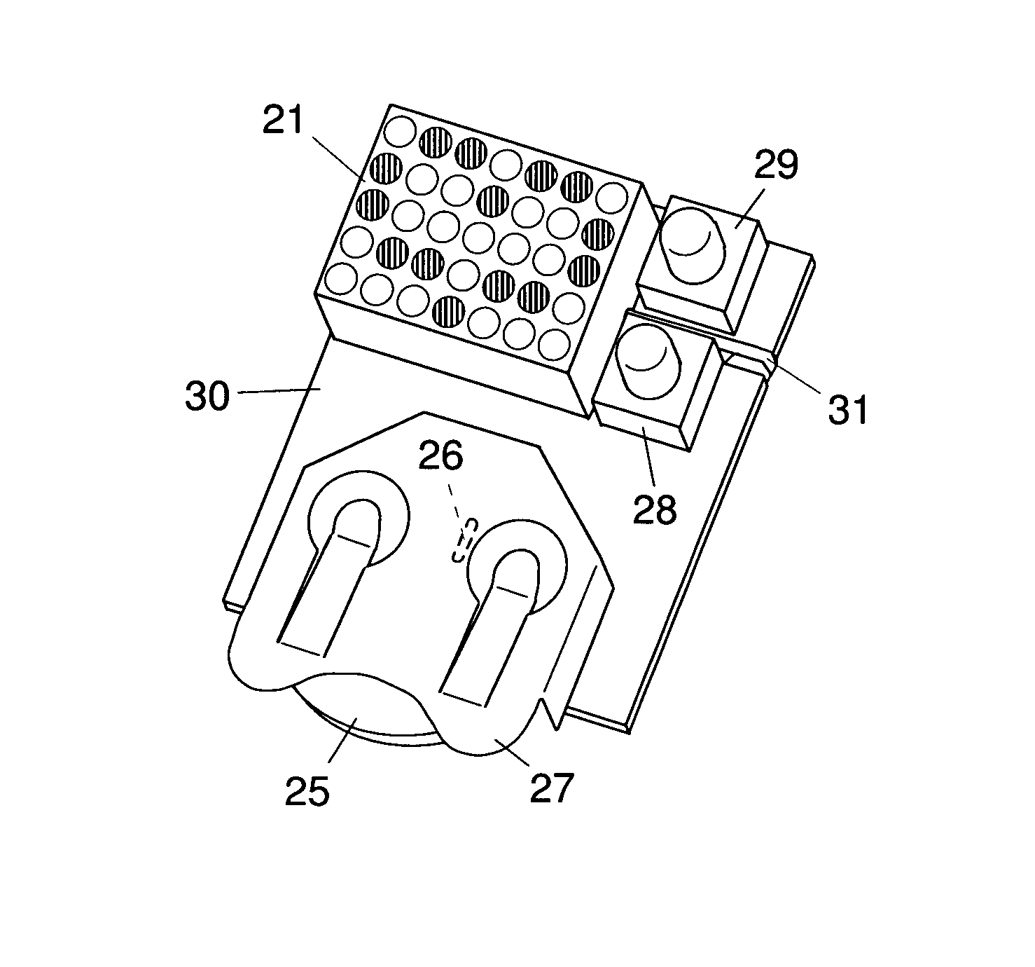
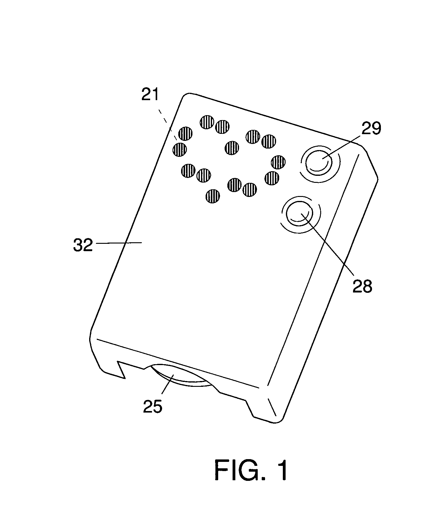
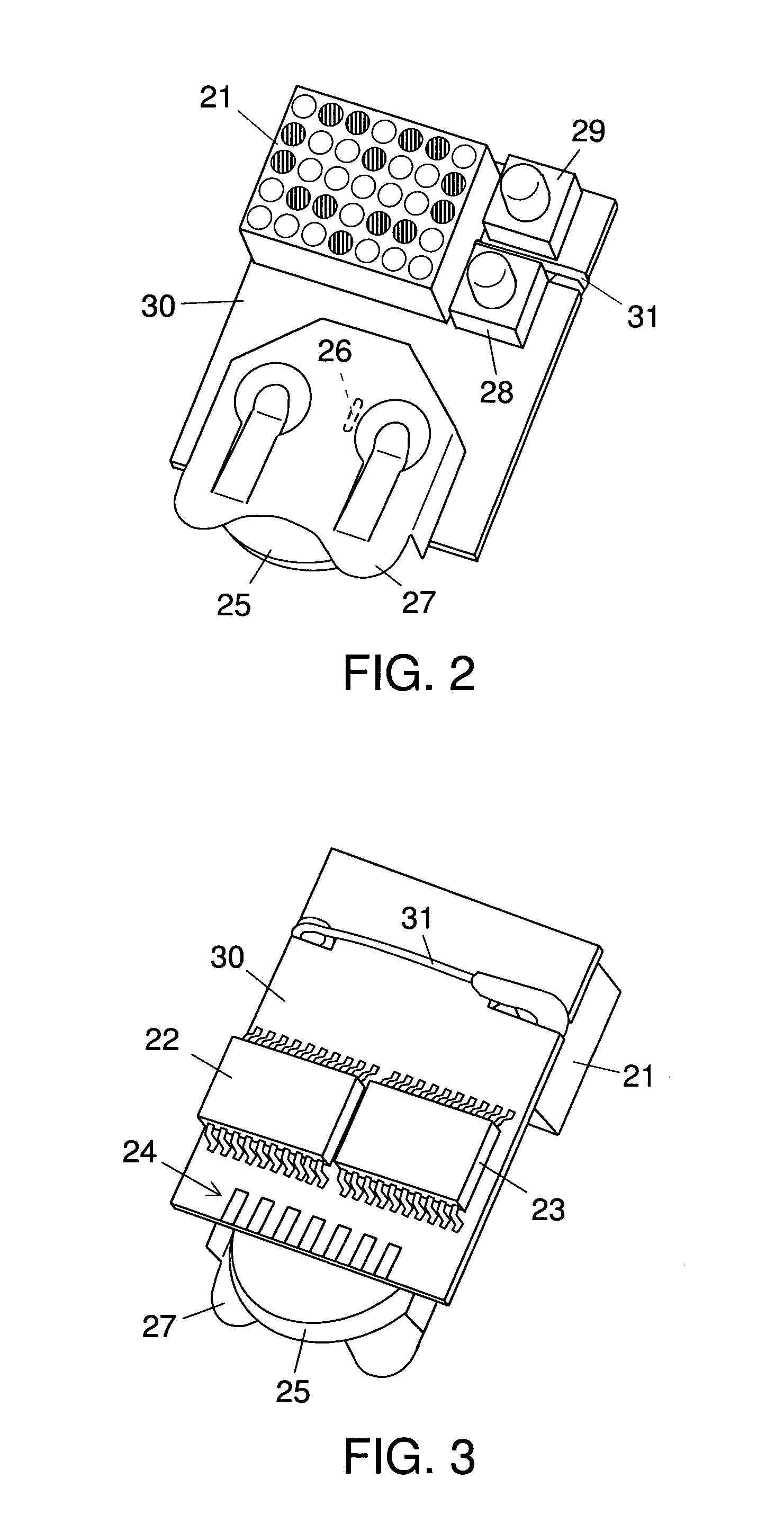
[0042]FIGS. 1-3 show, from different perspectives, a preferred embodiment of a device formed in accordance with the inventive systems, suitable for wearing as an illuminated ornament, as decorative jewelry or to advertise a message.

[0043]In that embodiment, the display is formed of an array of LED's in a matrix 21. The control circuit consists of a printed circuit board (PCB) 30, a microcontroller IC (MCU) 22 and an octal D flip-flop IC 23, both supported on the rear surface of PCB 30. The front surface of PCB 30 supports a wire link 26, a battery holder 27 for the compact power source battery 25, mode button 28 and value button 29, and programming connector 24, formed from some of the conducting tracks on PCB 30 and having seven edge fingers spaced at 2.54 mm centers. The device can be attached to clothing by safety pin 31, attached to the rear.

[0044]The components on the front surface of PCB 30 are supported by through-hole-soldering, and the components on the rear surface are sup...


PUM


Abstract

An electronic ornament that can be worn or attached to or suspended from an object has an LED matrix (21) capable of displaying a user-selected message from a preprogrammed set of graphic symbols or a user-programmed arbitrary pattern or animation. A safety pin (31) or other fastener (34) attaches the ornament to a wearer or to an object, making the display readable by others during conversations and gatherings from a distance of several meters. The user can select the message or pattern using only two buttons (28) and (29), and the selection is retained even when battery (25) is removed. The LED display (21) scrolls messages horizontally such that more than one average text character but less than one average word is visible at a time, making the display surprisingly readable yet economical and small enough to make it easy to wear or use as a lightweight ornament.

Description

COPYRIGHT STATEMENT[0001]The printed circuit layout in FIG. 4 and the computer source code in FIGS. 9A, 9B, and 10 are subject to copyright protection. The copyright owner has no objection to the facsimile reproduction by anyone of the patent document or the patent disclosure, as it appears in the Patent and Trademark Office patent files or records, but otherwise reserves all copyright rights whatsoever.FIELD OF THE INVENTION[0002]This invention relates to electronic ornaments, specifically to electronic jewelry or ornaments that can display character-based messages and non-character symbols, graphics, animations, and other visual patterns.BACKGROUND OF THE INVENTION[0003]The use of LED's for light-emitting displays on a variety of objects is well known.[0004]Rectangular matrices of LED's with appropriate control circuitry, to display scrolling messages of any length, including symbols, graphics, and animated images, are often seen in public places (one famous example is in Times Sq...

Claims


Application Information

Patent Timeline
Patent Type & Authority Patents(United States)
IPC IPC(8): G09G3/32
CPCG09G5/346G09G5/343G09G3/32G09G3/2018
Inventor HERZEN, BRIAN VONKEENAN, DAVID C.
Owner RAPID PROTOTYPES
Learn More