Locatable dielectric optical fiber cable having easily removable locating element

a dielectric optical fiber and locating element technology, applied in the direction of optics, fibre mechanical structures, instruments, etc., can solve the problems of lack of reliable locating equipment, conductive elements are prone to induced currents, and can be easily damaged, so as to achieve convenient detachable torn, easy to remove and detectable locating elements, and adequate jacket material coverage

Active Publication Date: 2007-12-25
SUMITOMO ELECTRIC LIGHTWAVE
View PDF11 Cites 47 Cited by
  • Summary
  • Abstract
  • Description
  • Claims
  • Application Information

AI Technical Summary

Benefits of technology

[0009]It is another object of the present invention to provide a dielectric optical fiber cable having an easily removable and detectable locating element.
[0010]It is another object of the present invention to provide a dielectric optical fiber cable having a detectable locating element associated therewith which is designed so as to be easily detachable torn along the length of the optical fiber cable.

Problems solved by technology

Conductive elements are prone to carry induced currents, which are potentially lethal, due to proximity to power lines above and below ground.
Conductive elements are also prone to damage from lightning strikes to ground.
The challenges with magnetically locatable cables continue to be: (1) lack of reliable locating equipment; (2) the ability to accurately locate the cable is prone to errors depending on soil type, soil conditions, and soil content (i.e. density, content of iron bearing particles or rocks, etc.); and (3) cable proximity to other cables, particularly cables which induce magnetic fields such as power cables.

Method used


Image

  • Locatable dielectric optical fiber cable having easily removable locating element
  • Locatable dielectric optical fiber cable having easily removable locating element
  • Locatable dielectric optical fiber cable having easily removable locating element

Examples


Embodiment Construction

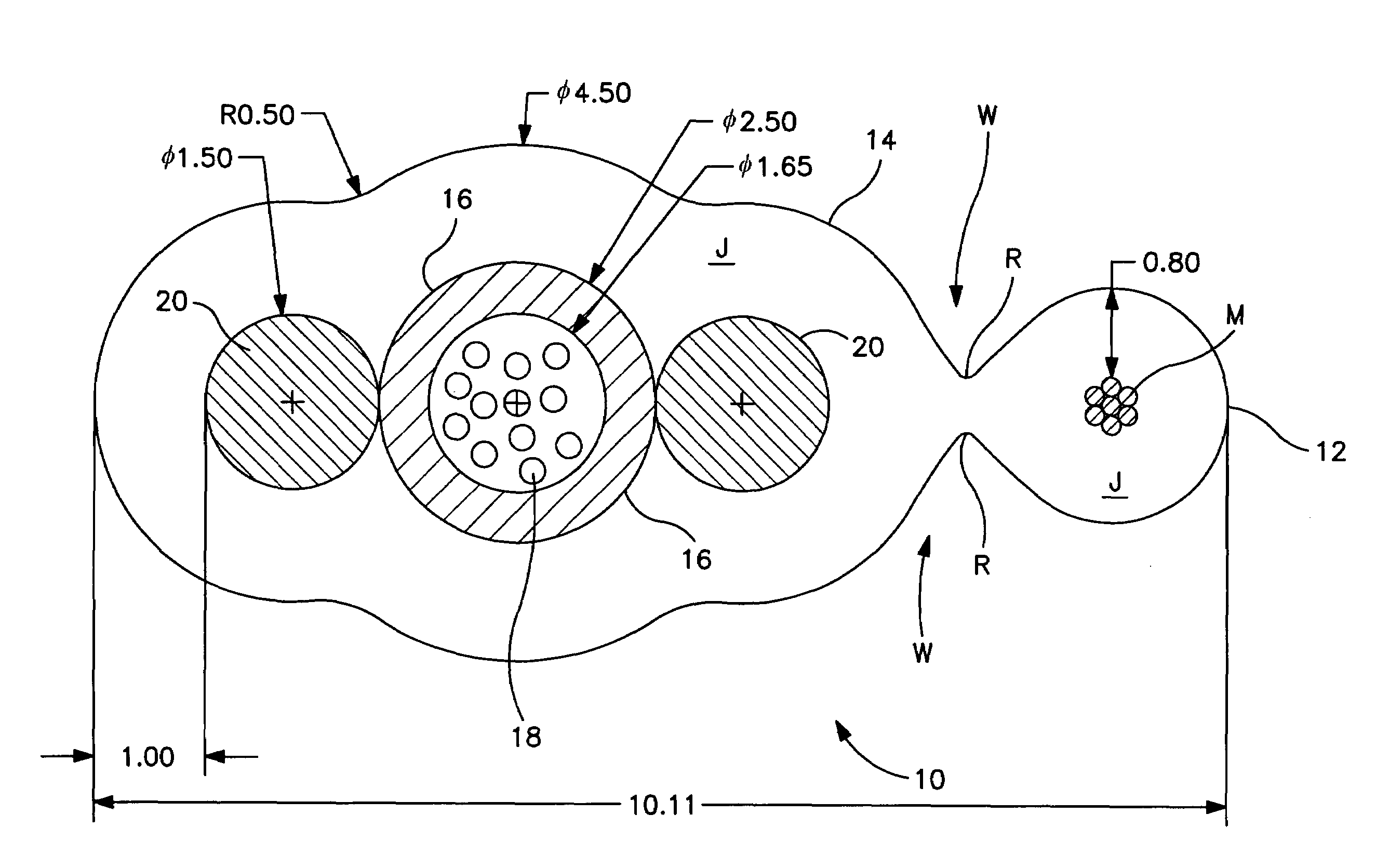
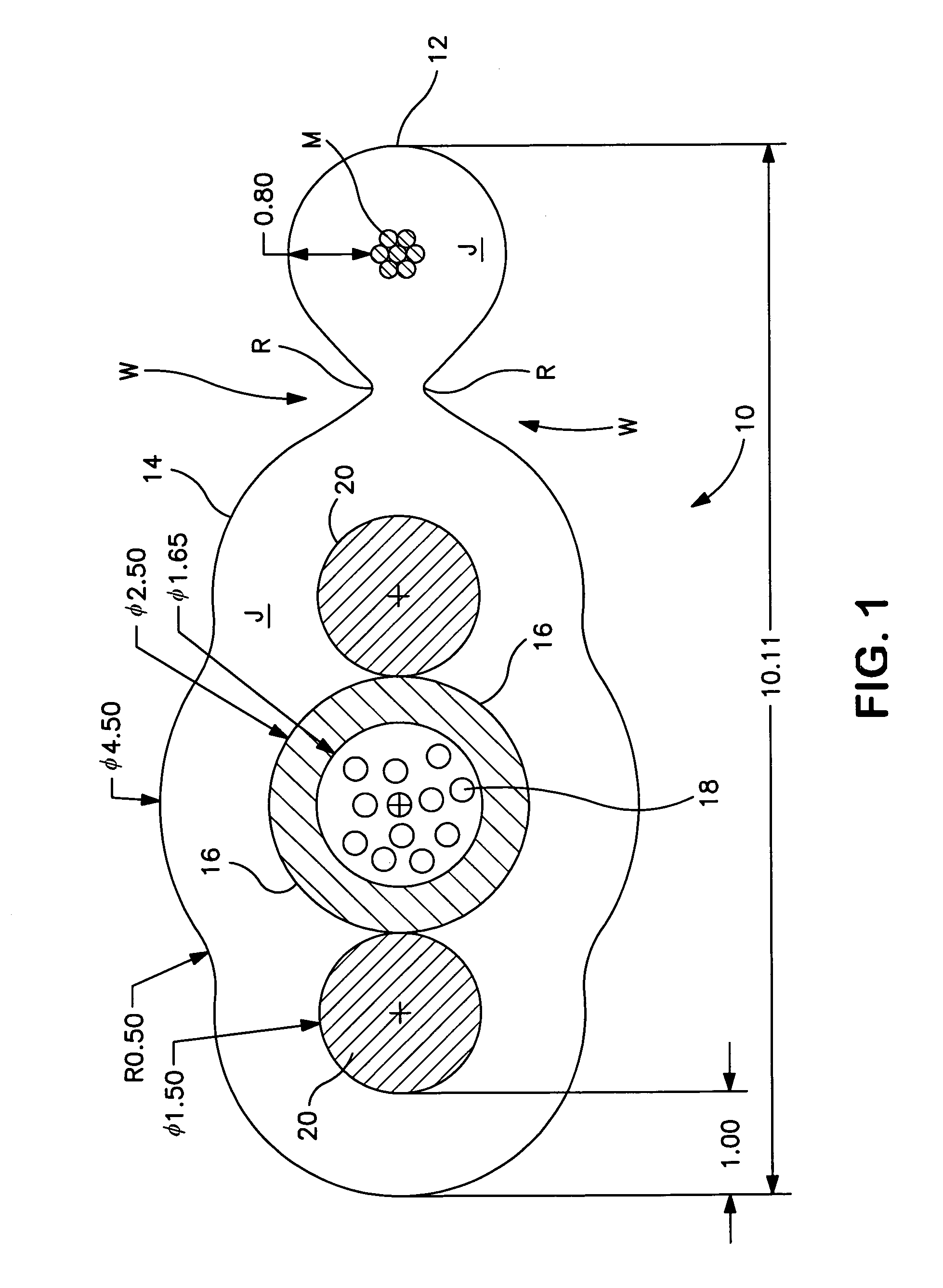
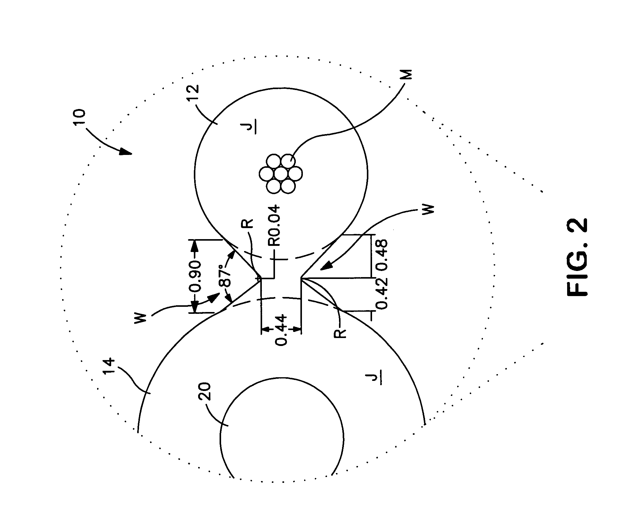
[0015]As is well known to those skilled in the art, although optical fiber cables represent a large portion of the outside plant network, subscriber access distribution and drop cables are dominantly copper-based products, either twisted pair or co-axial designs. It is a common practice today to determine the location of buried cables using electrical properties inherent to metals such as copper. Since optical fiber cables do not have copper and can be totally dielectric, metallic elements may be incorporated into the cables to facilitate locating the cables. However, any metallic element that enters an enclosure or premise must be grounded for safety reasons. Grounding requires additional installation time and hardware. An innovative solution is required to make an optical fiber drop cable locatable while eliminating the need for grounding of the optical fiber cable.

[0016]Referring now to FIGS. 1 and 2 of the drawings, the cable design of the present invention consists of two disti...


PUM


Abstract

The present invention provides a dielectric optical fiber cable which is capable of being remotely detected while buried. Specifically, this invention incorporates a detectable and easily removable locating element which is attached to the optical fiber cable by a web defined by the jacket extending over both the optical fiber cable and the locating element. The web allows for the locating strand to be easily removed once separation of the locating element from the optical fiber cable is initiated. The web is designed to allow the initial tear to propagate into a precise longitudinal tear along a predetermined length of the optical fiber cable.

Description

TECHNICAL FIELD[0001]This invention relates to a locatable optical fiber cable. More particularly, the optical fiber cable of the invention has an easily removable locating element which is engineered to allow for propagation on a precise longitudinal tear once separation of the locating element from the optical fiber cable is initiated.RELATED ART[0002]Prior art consists of fiber cable designs that incorporate locating elements within the cable structure. The locating elements are typically conductive elements such as copper wires, steel or aluminum shields applied to the cable sheath, or metallic strength elements. Any conductive elements incorporated into the cable structure must be grounded at the terminal ends of the cable for safety reasons. Conductive elements are prone to carry induced currents, which are potentially lethal, due to proximity to power lines above and below ground. Conductive elements are also prone to damage from lightning strikes to ground. Prior art cable i...

Claims


Application Information

Patent Timeline
Patent Type & Authority Patents(United States)
IPC IPC(8): G02B6/44
CPCG02B6/447G02B6/4495G02B6/562G02B6/4431
Inventor ANDREWS, ROBERT J.CHASTAIN, SCOTT M.STOKES, STEPHEN R.MACKIE, GEORGE A.
Owner SUMITOMO ELECTRIC LIGHTWAVE
Why Eureka
Try Eureka