High conductance cryopump for type III gas pumping

a cryopump and high conductance technology, which is applied in the direction of positive displacement liquid engines, separation processes, lighting and heating apparatus, etc., can solve the problems of reducing the accessibility of non-condensables to the adsorbent, and achieve the effect of high conductance, rapid collection of type iii gases, and improved conductan

Active Publication Date: 2008-01-01
EDWARDS VACUUM LLC
View PDF52 Cites 25 Cited by
  • Summary
  • Abstract
  • Description
  • Claims
  • Application Information

AI Technical Summary

Benefits of technology

[0010]In certain applications such as ion implantation, Type II gases are not prevalent, and loading of the cryopump is dominated by Type III hydrogen gas. Recognizing that, the present designs are based on a lesser concern for capture of Type II gases and a lesser concern for protecting the adsorbent from Type I and Type II gases, while opening the cryopumping array to improve conductance to the adsorbent for rapid collection of Type III gases by the adsorbent. The disclosed embodiments provide a high conductance frontal array, a radiation shield shaped to focus gases toward the second stage cryopanel and an open second stage cryopanel architecture, though implementation of the invention need not include all of these features.

Problems solved by technology

The chevrons, however, decrease the accessibility of the non-condensables to the adsorbent.

Method used


Image

  • High conductance cryopump for type III gas pumping
  • High conductance cryopump for type III gas pumping
  • High conductance cryopump for type III gas pumping

Examples


first embodiment

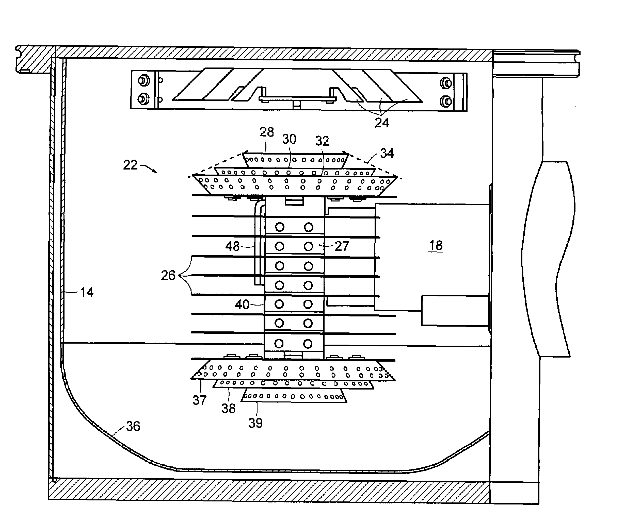
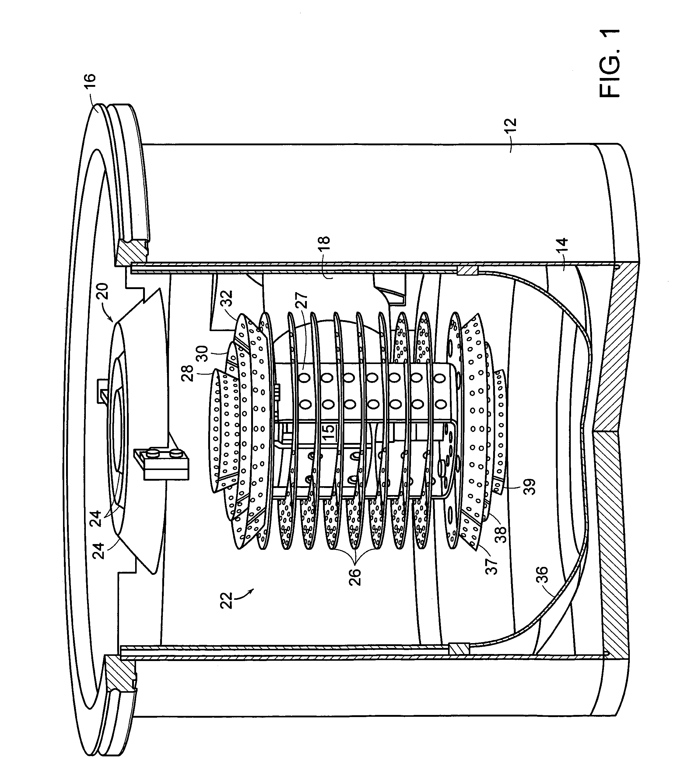
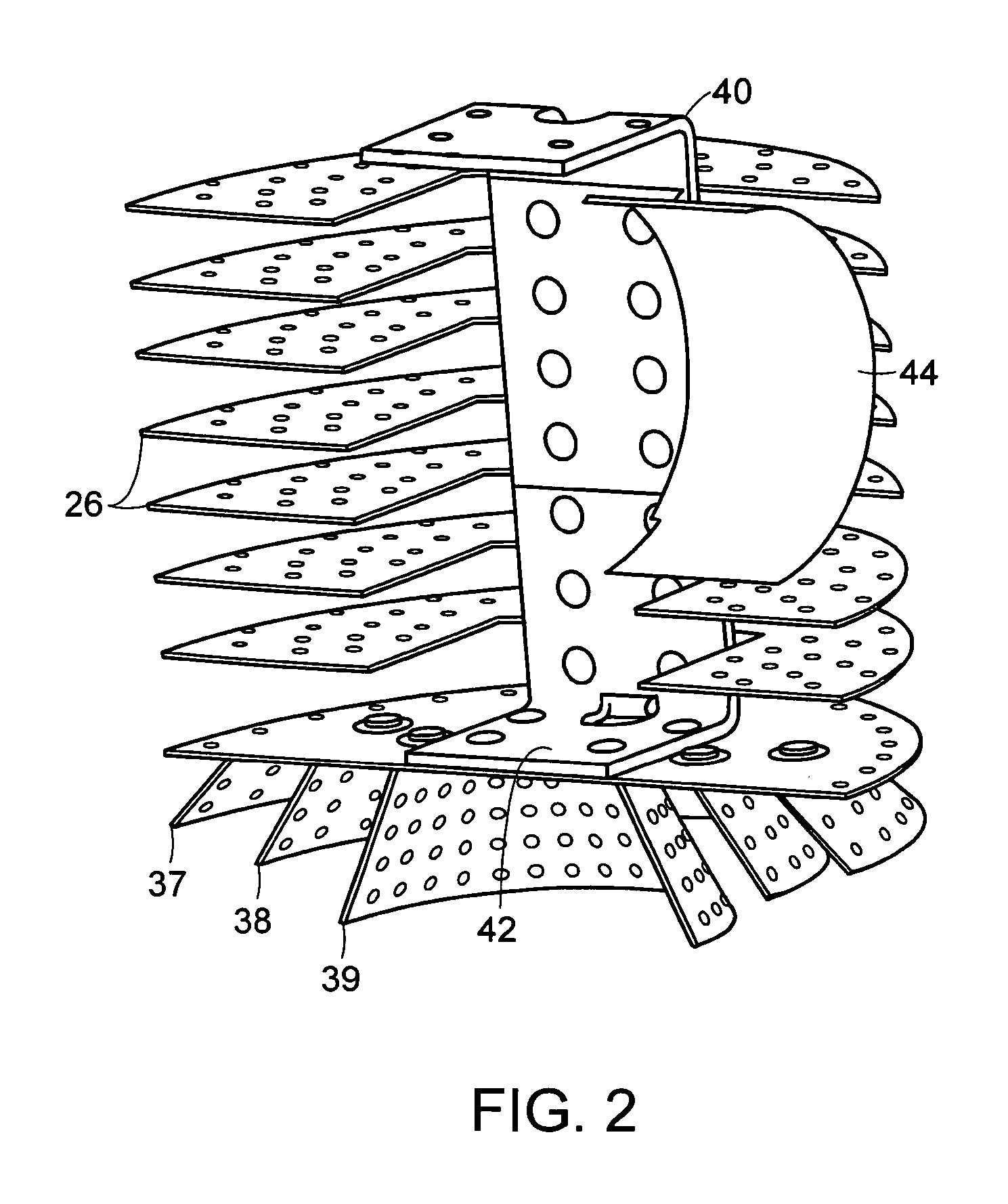
[0040]FIGS. 6-10 illustrate another embodiment of the invention. In this embodiment, the radiation shield 14 and frontal cryopanel 20 are similar to those found in the Similarly, the second stage cryopanel has an open design in which flat baffles are covered with adsorbent which is exposed to direct line of sight from the surrounding radiation shield or frontal opening. This embodiment, however, allows for fewer baffle parts and increased surface area. In this embodiment, the array is formed of discs which are fanned to define a generally ball shaped array. This design also relies on two baffle assemblies, one of which is illustrated in FIG. 7. The semi-circular discs are mounted to a bracket 62 having a vertical section 64 and incrementally sloping sections at either end. Four discs 66 are mounted to the vertical portion of the bracket and are thus horizontal. Three discs at each end of the bracket are angled outwardly and toward a respective end of the radiation shield. A final d...

second embodiment

[0042]A typical prior art cryopump having a 400 mm diameter has a capture rate at 72° F. of about 12,000 liters per second for hydrogen and a capture probability of hydrogen of about 22%. In an implementation of the first disclosed embodiment, a 320 mm diameter system, that is one having about two-thirds the opening area of the 400 mm system, has a capture rate of about 11,000 liters per second and a capture probability of about 31%. An implementation of the second disclosed embodiment having a 320 mm diameter obtains a capture rate of about 13,000 liters per second and a capture probability of about 37%. As another comparison, a conventional 250 mm system has a capture rate of about 4,500 liters per second with about 21% capture probability of hydrogen. A 250 mm system according to the invention obtained a 7,000 liter per second capture rate with about 32% capture probability of hydrogen.


PUM

PropertyMeasurementUnit
diameteraaaaaaaaaa
diameteraaaaaaaaaa
diameteraaaaaaaaaa

Abstract

A cryopump provides for high pumping speed of Type III gases. An open configuration of a frontal array provides high conductance of gases into a radiation shield which is shaped to focus gases toward a second stage array. The second stage array has an open configuration of baffles coated with adsorbent. Substantially all of the adsorbent has a direct line of sight to the radiation shield or to the opening in the radiation shield, and substantially all of the baffles are coated with adsorbent. In one form, the second stage cryopump array comprises an array of discs fanned to define a generally ball shaped envelope.

Description

BACKGROUND OF THE INVENTION[0001]Cryopumps currently available, whether cooled by open or closed cryogenic cycles, generally follow the same design concept. A low temperature second stage array, usually operating in the range of 4-25 degrees K., is a primary pumping surface. This surface is surrounded by a high temperature cylinder usually operated in the temperature range of 40-130 degrees K., which provides radiation shielding to the lower temperature array. The radiation shield generally comprises a housing which is closed except at a frontal array positioned between the primary pumping surface and the chamber to be evacuated. This higher temperature, first stage, frontal array serves as a pumping site for high boiling point gases such as water vapor, known as Type I gases.[0002]In operation, high boiling point gases such as water vapor are condensed on the frontal array. Lower boiling point gases pass through the frontal array and into the volume within the radiation shield. Typ...

Claims


Application Information

Patent Timeline
Patent Type & Authority Patents(United States)
IPC IPC(8): B01D3/12
CPCF04B37/08F04B37/02F04B37/04Y02E60/36F04B25/00F04B37/085F04B2205/065F04B2205/112F05B2220/61F25B9/14Y10S417/901
Inventor BARTLETT, ALLEN J.NORDBORG, JOHNTHOMPSON, BRIAN
Owner EDWARDS VACUUM LLC
Why Eureka
Try Eureka