Combustion chamber pressure sensor equipped with damper body for attenuating transmitted engine vibration

a technology of damper body and combustion chamber, which is applied in the field of pressure sensors, can solve the problems of lowering the accuracy of pressure measurement, prior art subject, and noise in the pressure measurement signal, and achieve the effect of increasing the accuracy of the pressure measurement signal

Inactive Publication Date: 2008-01-01
DENSO CORP +1
View PDF22 Cites 14 Cited by
  • Summary
  • Abstract
  • Description
  • Claims
  • Application Information

AI Technical Summary

Benefits of technology

[0008]As a result of providing the damping body, vibration (caused by running of the engine) that is transmitted to the housing from the engine block is effectively attenuated, thereby reducing the level of such vibration that is transmitted to the pressure sensing element directly from the housing, or that is transmitted from the housing to the pressure transmitting member and so to the pressure sensing element. The level of noise resulting from such vibration, contained in a pressure measurement signal that is generated by the pressure sensing element, can thereby be substantially reduced by comparison with the prior art, and the pressure sensing accuracy can be accordingly increased.
[0009]The damping body is disposed on the housing without being in contact with to the pressure sensing element or the pressure transmitting member. It is thereby ensured that pressure variations that occur within the combustion chamber are transmitted to the pressure sensing element without being attenuated by the damping body, so that no deterioration of the pressure sensing accuracy can occur due to such attenuation.
[0010]The damping body may be disposed in contact with an external or an external circumferential surface of the housing. A large amount of surface area of the housing can thereby be held in direct contact with the damping body, so that effective attenuation of vibration can be achieved.
[0015]According to another aspect, a combustion chamber pressure sensor according to the present invention can be integrally formed in a combination ignition coil, spark plug and pressure sensor. The ignition coil and spark plug components of such a combination device include a primary coil and secondary coil of the ignition coil, a central electrode, a ground electrode, and an insulator that is of elongated tubular form and encloses the secondary coil and the central electrode and is enclosed by the primary coil. The primary coil is sheathed in the housing, and the ground electrode is attached to the front end of the housing, with a front end of the insulator being disposed adjacent to the ground electrode, exposed to the interior of the combustion chamber. The tip of the rear end of the insulator is disposed in contact with the pressure sensing element, such that the pressure sensing element is held between that rear end of the insulator and a retaining member at the rear end of the housing. Thus the insulator (in addition to its electrical insulation function) performs the function of the aforementioned pressure transmitting member of the combustion chamber pressure sensor. The housing of the combination spark plug and pressure sensor is provided with a damping body as described above, so that the advantage of increased accuracy of the pressure measurement signal can also be obtained with such a combination spark plug and pressure sensor.
[0016]In that case, the primary coil of the ignition coil may be potted in a synthetic plastic material that is viscoelastic, such as epoxy resin, molded to form a tubular member. That tubular member can be disposed within the housing, enclosing the insulator, with the outer circumferential surface of the tubular member in contact with the internal circumferential surface of the housing, and with a gap between the inner circumferential surface of the tubular member and the outer circumferential surface of the insulator. The tubular body containing the primary coil thereby serves as an effective damping body.
[0018]The housing of the combination glow plug and pressure sensor is provided with a damping body as described above, so that the advantage of increased accuracy of the pressure measurement signal can also be obtained with such a combination glow plug and pressure sensor.

Problems solved by technology

However a basic problem exists with prior art subjected to the pressure of the combustion chamber and generates a pressure measurement signal accordingly.
In the prior art, a substantial level of engine vibration is transmitted through the engine block and reaches the pressure sensing element, and results in occurrence of noise in the pressure measurement signal.
This noise results in lowering of the pressure measurement accuracy.
In particular, the existence of such noise renders it difficult to accurately detect the occurrence of engine knock, by monitoring pulsations in the pressure measurement signal.

Method used


Image

  • Combustion chamber pressure sensor equipped with damper body for attenuating transmitted engine vibration
  • Combustion chamber pressure sensor equipped with damper body for attenuating transmitted engine vibration
  • Combustion chamber pressure sensor equipped with damper body for attenuating transmitted engine vibration

Examples


first embodiment

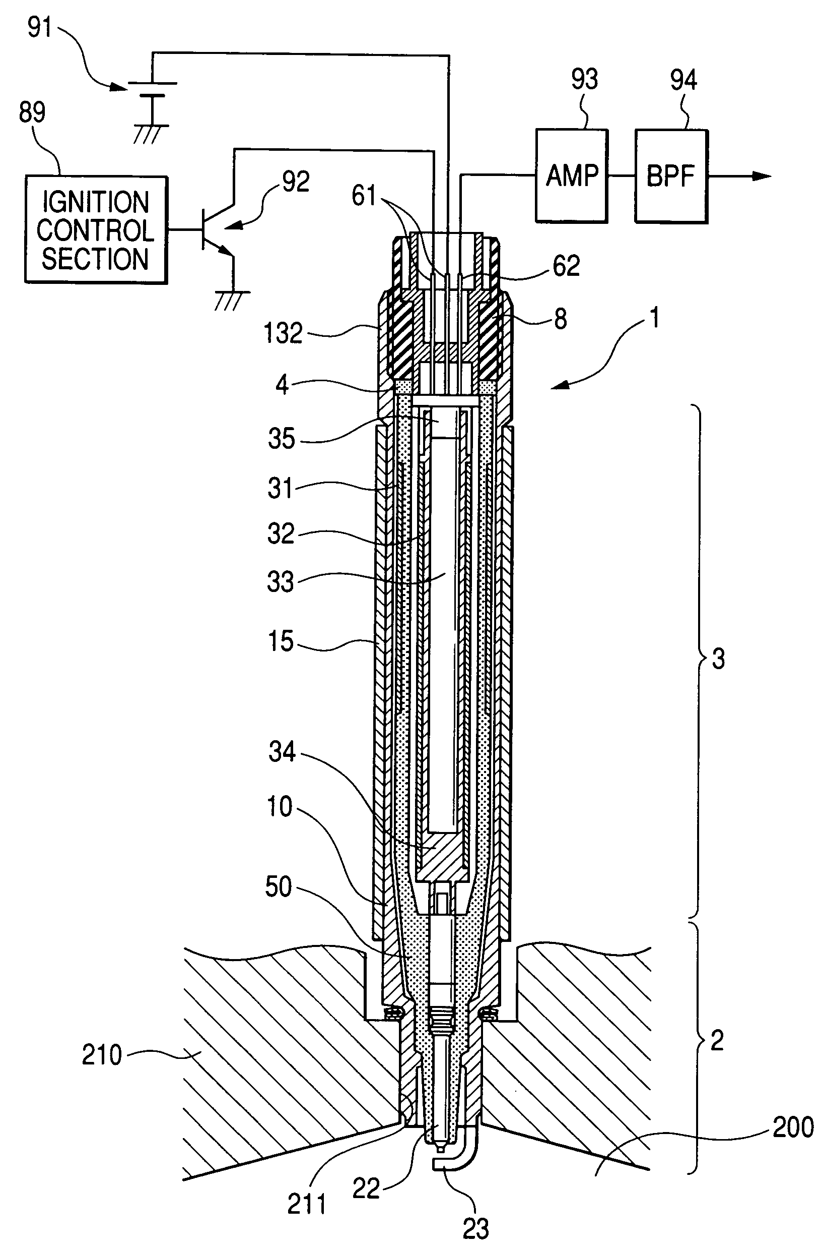
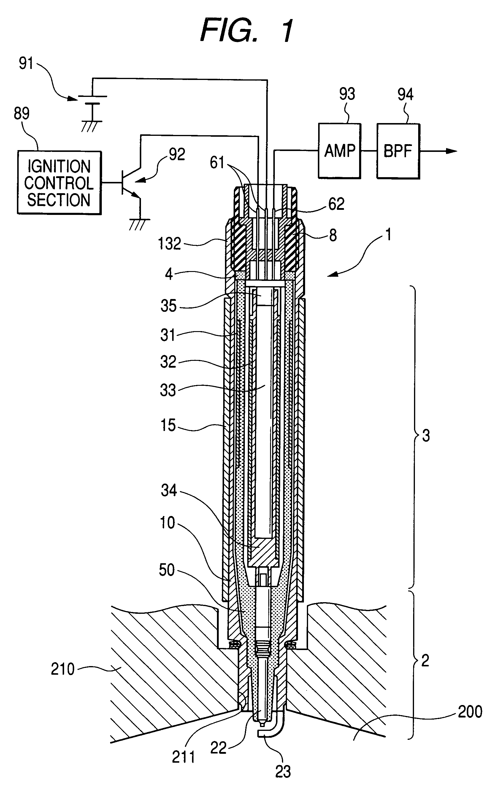
[0036]A first embodiment will be described referring to FIGS. 1 to 7. As shown in cross-sectional view in FIG. 1, this embodiment is a combustion chamber pressure sensor that is integrally combined with an ignition coil and spark plug. The combination device, designated by reference numeral 1 in FIG. 1, will be referred to in the following simply as a combination spark plug and sensor. The combination spark plug and sensor 1 includes a housing 10 that is fixedly attached in an engine block 210 of an internal combustion engine (only a part of the engine block 210 of that internal combustion engine being shown in FIG. 1), with the engine block 210 enclosing a combustion chamber 200. A pressure sensing element 4, which is of annular shape, is retained within the housing 10, with opposing annular faces of the pressure sensing element oriented at right angles to a central axis of the combination spark plug and sensor 1. An insulator 50, in addition to performing an electrical insulation ...

second embodiment

[0078]FIG. 8 shows a second embodiment, which is a combination glow plug and pressure sensor 102 that is integrated with a glow plug of a diesel engine. For brevity of description, components having identical functions and basically similar configurations to corresponding components of the first embodiment are designated by identical reference numerals to those of the first embodiment. With the second embodiment, the housing 10 encloses an axially extending conductor rod 72 which is electrically connected to the heater 71 of the glow plug, for supplying electrical power to the heater 71. The heater 71 is fixedly attached to the front end of the conductor rod 72. The heater 71 and conductor rod 72 in combination constitute a central axial member 70, which functions as the pressure transmitting member of this embodiment, for transmitting the pressure within a combustion chamber to the pressure sensing element 4.

[0079]A retaining member 8 of this embodiment is fixed within the inner ci...

third embodiment

[0082]A third embodiment will be described referring to FIG. 9. This is a combustion chamber pressure sensor 103 that is a dedicated pressure sensor, not integrated with other devices. The combustion chamber pressure sensor 103 includes a pressure-receptive diaphragm 74 which is located close to the tip of the front end of the housing 10, within the housing 10. The housing 10 is fixed in an engine block 210, with the pressure-receptive diaphragm 74 exposed to the interior of a combustion chamber of an internal combustion engine. An outer circumferential portion of the pressure-receptive diaphragm 74 is welded to the housing 10 (the weld not being shown in the drawings), to attach the pressure-receptive diaphragm 74 to the housing 10. The pressure-receptive diaphragm 74 is also attached to the tip of the front end of a pressure transmitting rod 75, which functions as the pressure transmitting member of this embodiment, with the end face of the rear end of the pressure transmitting ro...


PUM


Abstract

A combustion chamber pressure sensor for an internal combustion engine includes an elongated pressure transmitting member having one end exposed to the interior of an engine cylinder and the opposite end contacting a pressure sensing element which generates a pressure measurement signal, the pressure transmitting member and pressure sensing element being contained within an elongated housing. A damping body formed of a viscoelastic material is disposed on an outer or inner circumferential surface of the housing, for reducing an amount of engine vibration that is transmitted to the pressure sensing element and thereby reducing noise in the pressure measurement signal.

Description

[0001]This application is based on and incorporates herein by reference Japanese Patent Application No. 2004-319735 filed on Nov. 2, 2004.BACKGROUND OF THE INVENTION[0002]1. Field of Application[0003]The present invention relates to a pressure sensor for measuring the pressure within a combustion chamber of an internal combustion engine.[0004]2. Description of Related Art[0005]By measuring the pressure within a combustion chamber of an internal combustion engine, it becomes for example possible to detect occurrence of engine knock, thereby enabling the engine operation to be more closely controlled. A combustion chamber pressure sensor which is utilized for such a pressure measurement function may be an independent device, or may be integrated with another device that is installed in a combustion chamber. A combustion chamber pressure sensor may for example be integrally combined with an engine spark plug, or with a combined ignition coil and spark plug. This is described for exampl...

Claims


Application Information

Patent Timeline
Patent Type & Authority Patents(United States)
IPC IPC(8): G01M15/00
CPCG01L23/22
Inventor YORITA, HIROSHIMIWA, TETSUYAHIRAMATSU, HIROMI
Owner DENSO CORP
Why Eureka
Try Eureka