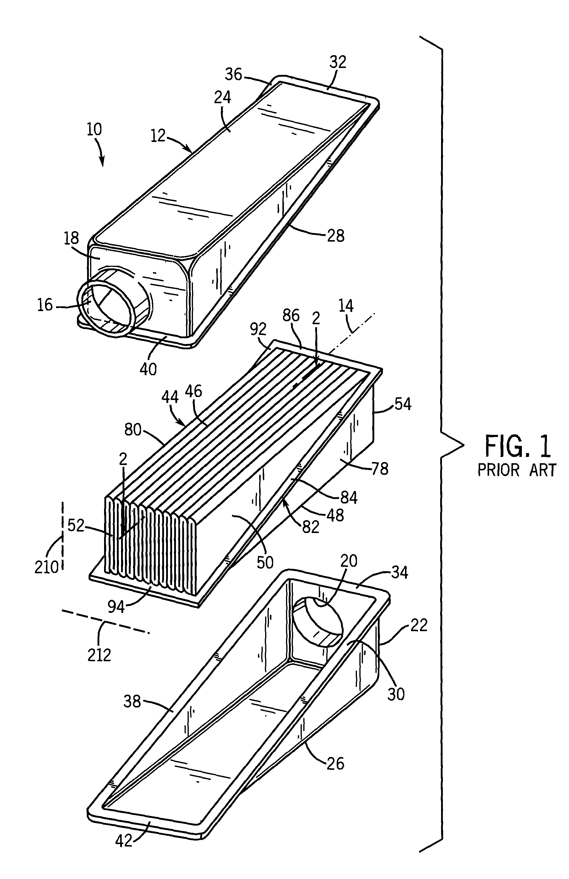
[0002]It is known in the prior art to use pleated filter blocks for various fluid filtering applications, including panel-type
air cleaners. In U.S. Pat. No. 6,482,247, incorporated herein by reference, a multi-panel fluid filter with equalized contaminant passages is designed to maximize usage of the volume of the filter housing. The '247 design produces a compact sized
filtration system that can be designed with conventional panel filters. The '247 design makes it possible to either reduce the filter size for a stated fluid flow rate or increase the fluid flow rate for a filter with a size comparable to a conventional panel filter. The unit contaminant capacity for the '247 filter is greater since nearly the entire volume of the filter housing accommodates
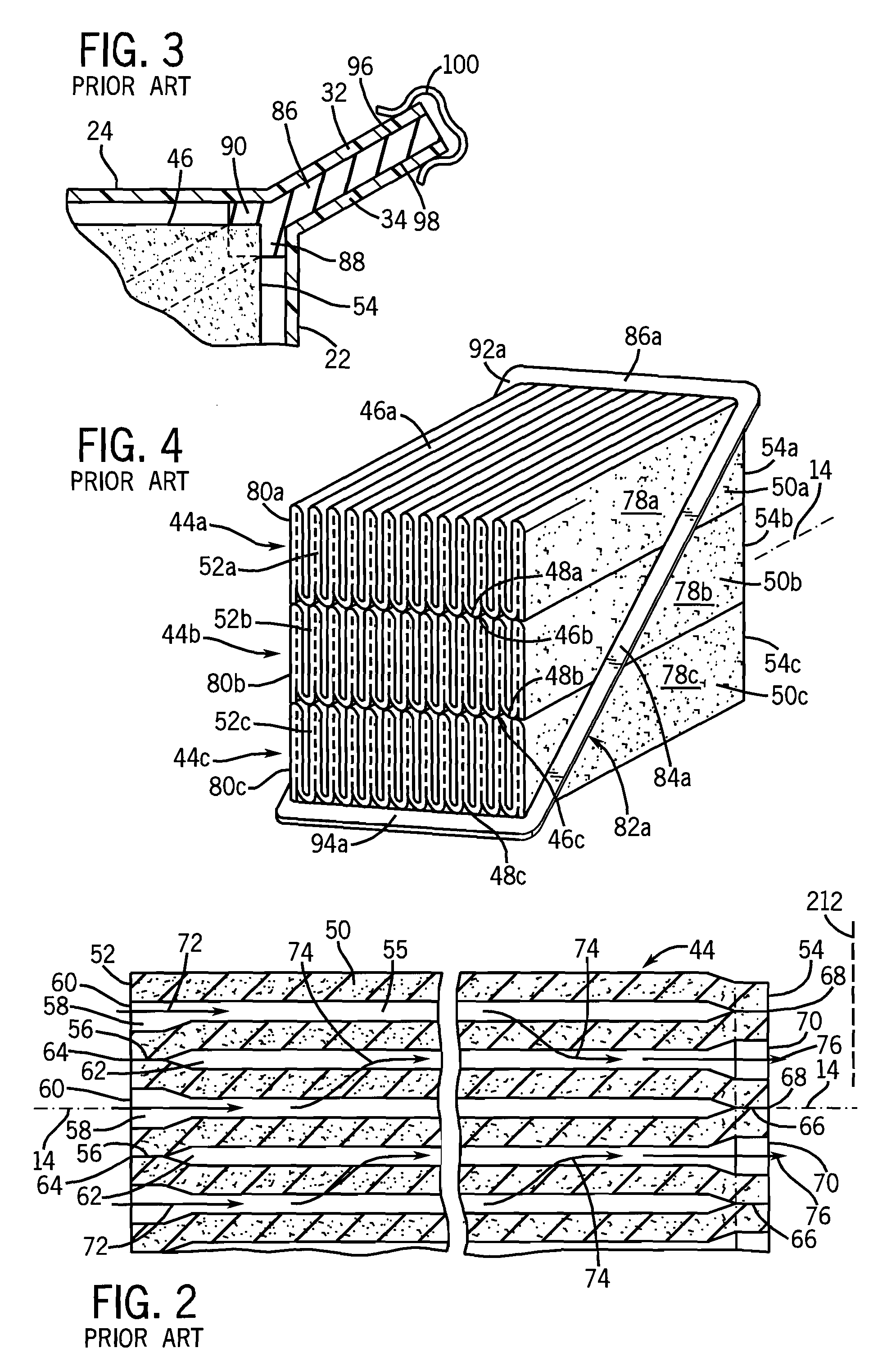
filter media. Individual filter panels are made using alternating seal technology. A gap is provided between individual panels, and a series of spacers or holders are attached to individual panels, as independent inserts, or attached to the filter housing as covers, and uniformly space the pleated elements, including in the case of less rigid pleats. The individual pleated filter elements are sealed by means of an
adhesive material and are merged with a leak free bond on one end and are open on the opposite end. The design prevents any contaminant from leaking without being filtered to the required level of particle size and concentration. The combined filter is sealed to the housing with a
gasket permanently attached to the multi-element outer perimeter or permanently attached to the filter and the housing. The latter is a disposable
filter design option. The gaps between the individual filter elements form flow passages that make it possible for contaminant particles to enter the pleated material through the filter front side between the alternately sealed pleats and through the space above or below the element. The filter front stays open to the flow, and the
filter media surface is loaded uniformly with contaminant particles. Because of this uniformly distributed contaminant cake, the surface of the filter media is fully and optimally utilized to achieve high contaminant loading in a small volume.
[0003]It is known in the prior art to provide parallel flutes or individual
layers of filter media to achieve high volume utilization of the filter housing. When the surface area of the media increases in such designs, the contaminant holding capacity also increases. However, the inlet of such filters can become clogged due to edge phenomena. For a fluid in motion, the
flute edges are
solid obstacles playing a similar role as single fibers due in filter media. Contaminant particles are captured by edges due to this inertial mechanism. Because
adhesive forces between the collected particles are usually greater (because they are the same material) than those between the
flute edge and the particles, additional particles are captured on previously captured contaminant, forming large clusters. These clusters can clog the flute openings and drastically increase filter pressure drop. Moreover, the particle aggregates formed on the edges of the flutes prevent the contaminants from entering the space downstream of the particle clusters.
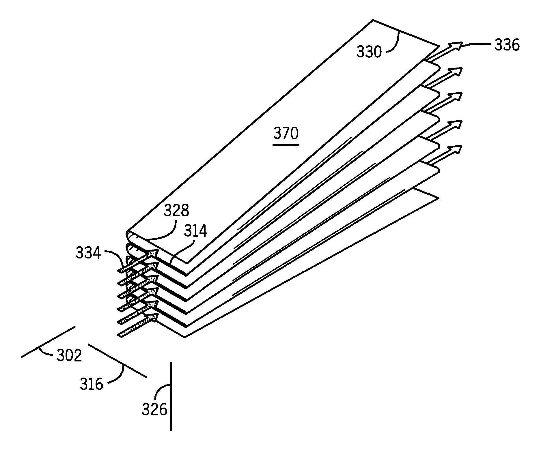
[0004]In the '247 patent, contaminant accumulation on the inlet face is significantly reduced. In contrast to previous designs, the contaminant will not clog the filter inlet because there are allowable contaminant passages around the individual pleated
layers of filter media. Contaminant holding capacity increases due to a more uniform flow field and maximum use of filter media surface. The contaminant cake is also distributed more uniformly along the entire
filter element length. Because of the uniform contaminant
mass distribution, filter pressure drop increases more slowly than previous designs, and filter life increases. Gaps in the multi-panel filter ensure more equalized flow and contaminant distribution to the filter media. The design enables the gaps to be large enough to
resist plugging from occasional large objects such as feathers, grass clippings, seeds, insects, etc., that enter the air
induction system in an
air filter application. The incorporation of such gaps also reduces pressure drop.

