Line-illuminating device and image-scanning device

a technology of image scanning and illumination device, which is applied in the direction of sensing by electromagnetic radiation, printing, instruments, etc., can solve the problem of difficulty in setting the density of light traveling inside the bar-shaped light guide above a certain level, and achieve the effect of high-precision line illumination

Inactive Publication Date: 2008-01-08
NIPPON SHEET GLASS CO LTD
View PDF4 Cites 21 Cited by
  • Summary
  • Abstract
  • Description
  • Claims
  • Application Information

AI Technical Summary

Benefits of technology

[0010]It is therefore an object of the present invention to provide a line-illuminating device which can increase the density of the energy of light traveling the inside a bar-shaped light guide.
[0014]According to another embodiment of the present invention, the substrate of the light-emitting unit is provided with three windows and each light-emitting element of the three primary colors is disposed in each window, wherein three bar-shaped light guides are provided to correspond to the three windows, respectively. With this arrangement, it is also possible to increase the density of light energy within the bar-shaped light guide.
[0016]According to the present invention, it is possible to make the coupling window formed on the substrate of the light-emitting unit smaller and as a result, a cross sectional area of the bar-shaped light guide can be made smaller. When the cross sectional area of the bar-shaped light guide is made smaller, the density of light energy traveling the inside the bar-shaped light guide is increased and, as a result, it is possible to brightly illuminate a narrow area of a document even though scattering dots formed on the bar-shaped light guide are made smaller.
[0018]In this manner, it is possible to provide an extremely high-precision line-illuminating device by applying the present invention to a facsimile machine, a copying machine, an image scanner and the like in which the bar-shaped light guide is provided close to a document surface.

Problems solved by technology

As a result, it is difficult to set the density of the energy of light traveling inside the bar-shaped light guide above a certain level.
When the density of the light energy is low, it is not possible to effect radiation with such directional characteristics as to brightly illuminate a narrow area of a document surface.

Method used


Image

  • Line-illuminating device and image-scanning device
  • Line-illuminating device and image-scanning device
  • Line-illuminating device and image-scanning device

Examples


Embodiment Construction

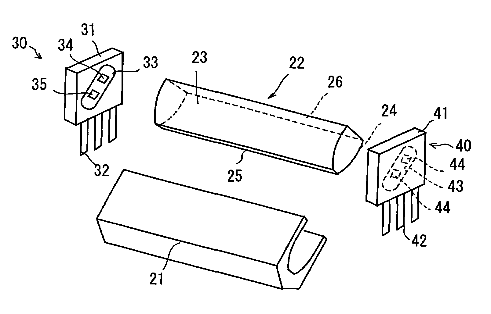
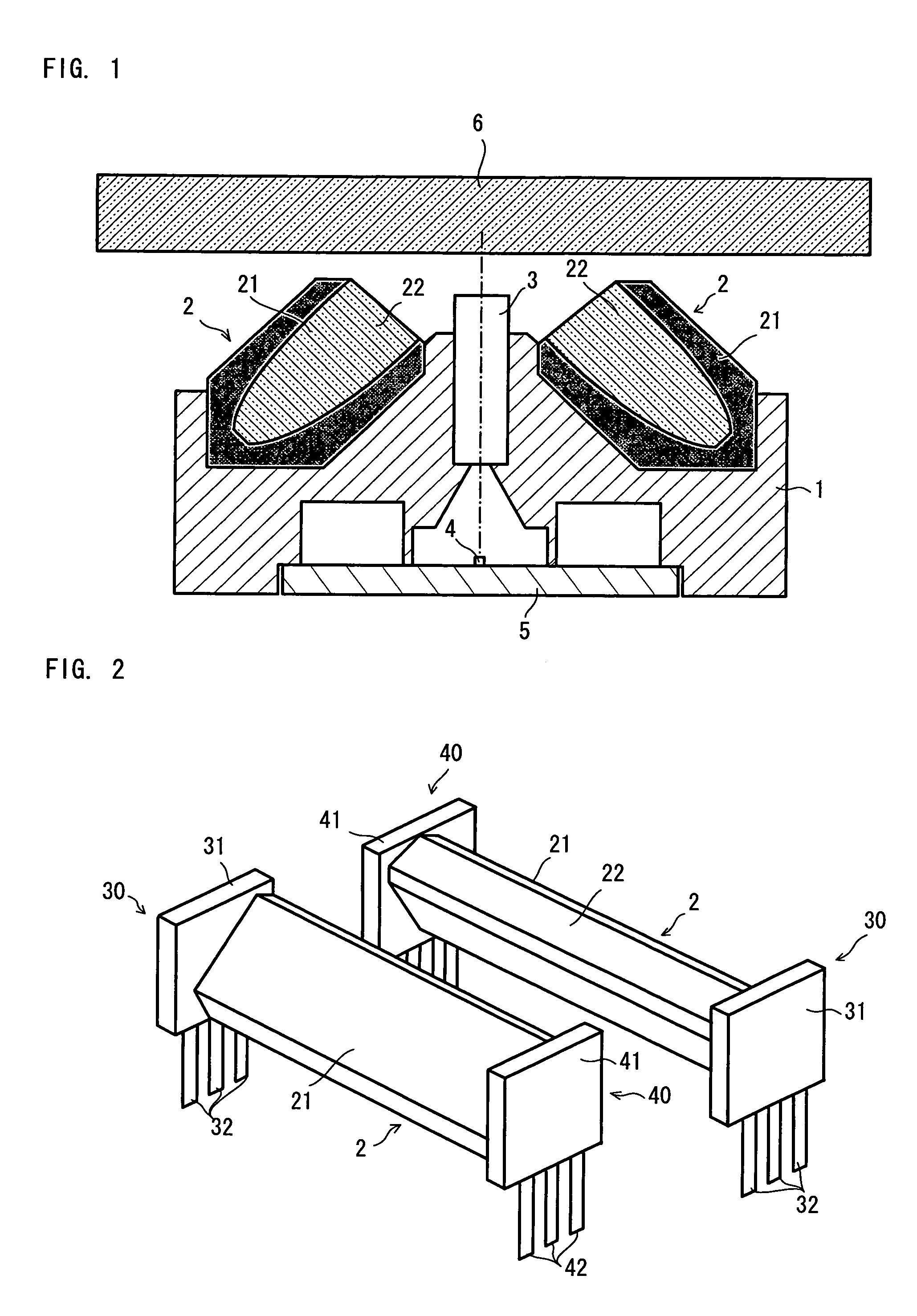
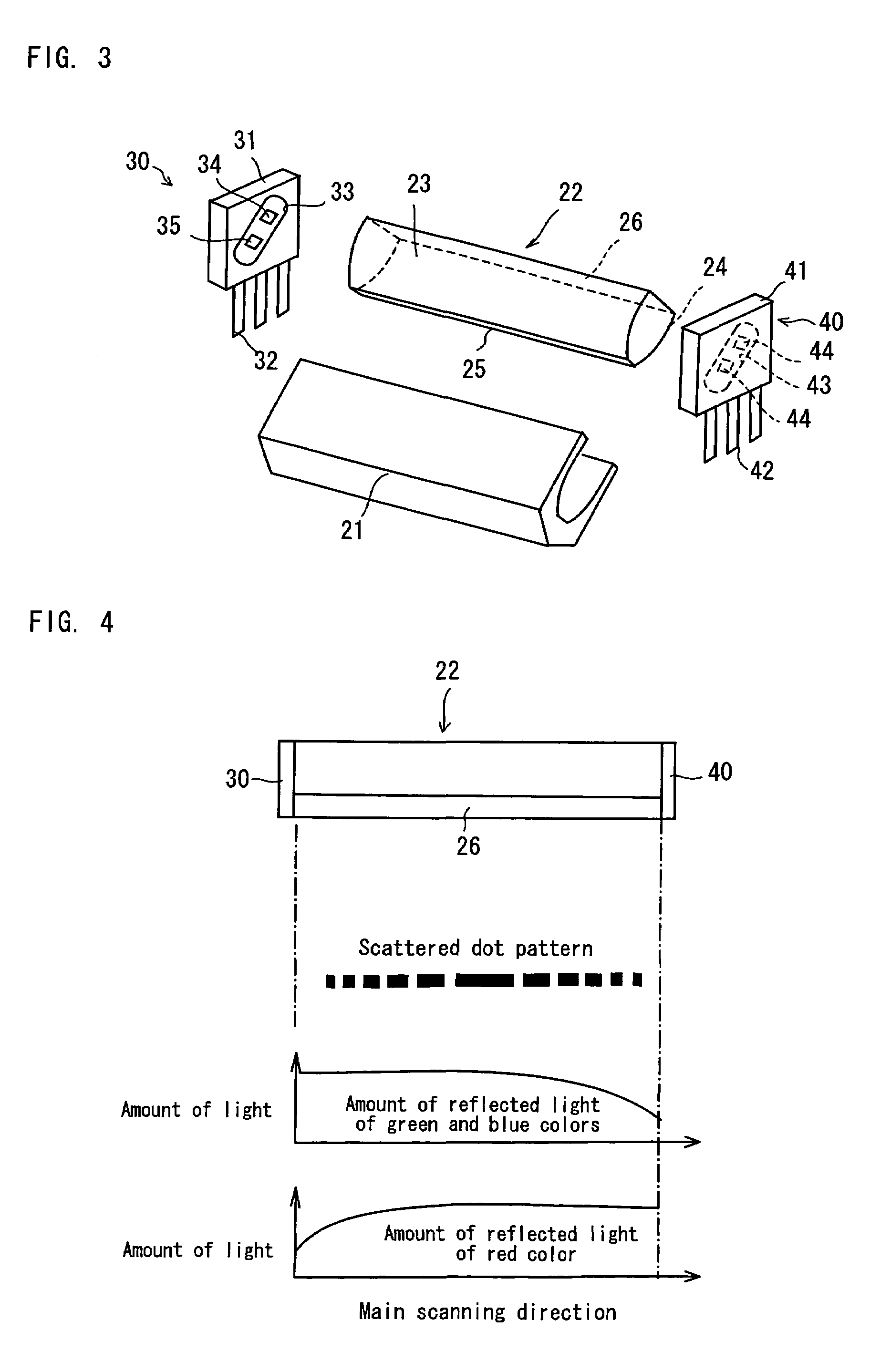
[0027]Preferred embodiments of the present invention will now be described with reference to the accompanying drawings. FIG. 1 is a cross-sectional view of a contact-type image sensor to which a line-illuminating device according to the present invention is applied. FIG. 2 is a perspective view of a pair of line-illuminating devices incorporated in the contact-type image sensor. FIG. 3 is an exploded perspective view of a line-illuminating device according to the present invention.

[0028]A contact-type image sensor is provided, in which two sets of line-illuminating devices 2 and 2 are incorporated in a holding body 1. A lens array 3 of an erecting unit magnification system is disposed within the holding body 1. Formed at the lower part of the holding body 1 is a plate 5 on which a line image sensor 4 is mounted. A document table 6 (i.e., a glass plate) is provided above the line-illuminating devices 2 and 2.

[0029]As shown in FIG. 3, the line illuminating device 2 comprises a white c...


PUM

PropertyMeasurementUnit
sizeaaaaaaaaaa
colorsaaaaaaaaaa
areaaaaaaaaaaa

Abstract

A line-illuminating device comprises a white casing, a bar-shaped light guide housed within the casing, and light-emitting units provided on opposite ends of the bar-shaped light guide. The light-emitting unit has a substrate forming a circuit on which a lead wire for power supply is installed. Formed on a surface of the substrate facing the bar-shaped light guide is a window for coupling in which a green-color light-emitting diode and a blue-color light-emitting diode are installed. Likewise, the light-emitting unit has a substrate on which a lead wire for power supply is installed. Formed on a surface of the substrate facing the bar-shaped light guide is a window for coupling in which two red-color light-emitting diodes are installed.

Description

BACKGROUND OF THE INVENTION[0001]1. Field of the Invention[0002]The present invention relates to a line-illuminating device having a bar-shaped light guide and a light-emitting unit and to an image-scanning device in which the line-illuminating device is incorporated.[0003]2. Description of the Background Art[0004]A contact-type image sensor (i.e., an image-scanning device) is used as a device for scanning a document using a facsimile machine, a copying machine, an image scanner and the like. The contact-type image sensor is provided with a line-illuminating device for linearly illuminating a document surface along a main scanning field.[0005]A line-illuminating device using a light guide is known. For example, Patent Document 1 proposes a line-illuminating device in which a light-emitting unit is provided on one end of the light guide and a light-scattering pattern is formed to diffuse and reflect the light from the light-emitting unit along the longitudinal direction of the light ...

Claims


Application Information

Patent Timeline
Patent Type & Authority Patents(United States)
IPC IPC(8): G06K7/10F21V8/00G03B27/54G02B6/00G06K7/14H04N1/028H04N1/04
CPCH04N1/02815H04N1/02835H04N1/02885H04N2201/03112H04N2201/03125H04N2201/03141H04N2201/03145D03D27/02D06C23/00D06P1/41D03D15/54
Inventor IKEDA, MAKOTONEMOTO, HIROYUKI
Owner NIPPON SHEET GLASS CO LTD
Why Eureka
Try Eureka