
Seat moving device for vehicle

a technology for moving devices and seats, applied in the direction of movable seats, roofs, transportation and packaging, etc., can solve the problems of premature deterioration of electric motors, and achieve the effect of preventing damage to the driving devi

Active Publication Date: 2008-01-08
TOYOTA SHATAI KK
View PDF13 Cites 46 Cited by
  • Summary
  • Abstract
  • Description
  • Claims
  • Application Information

AI Technical Summary

Benefits of technology

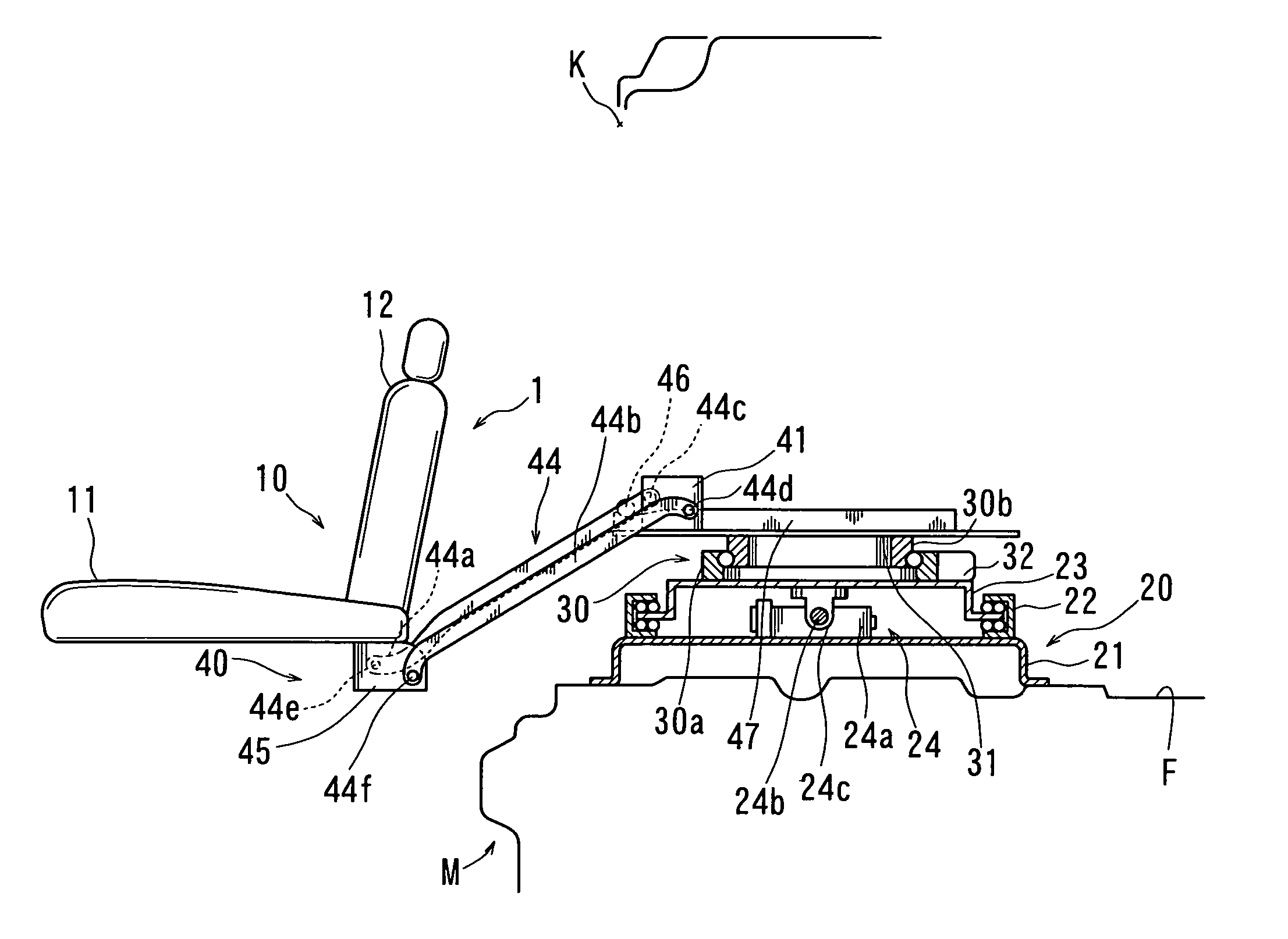
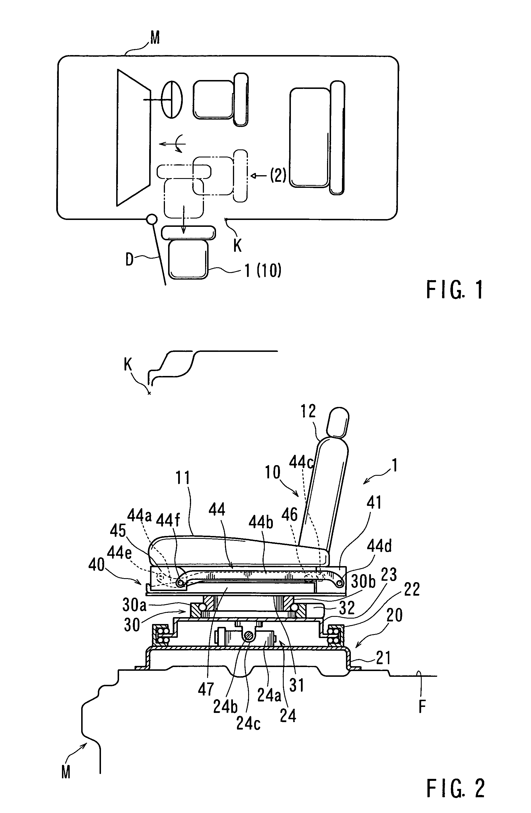
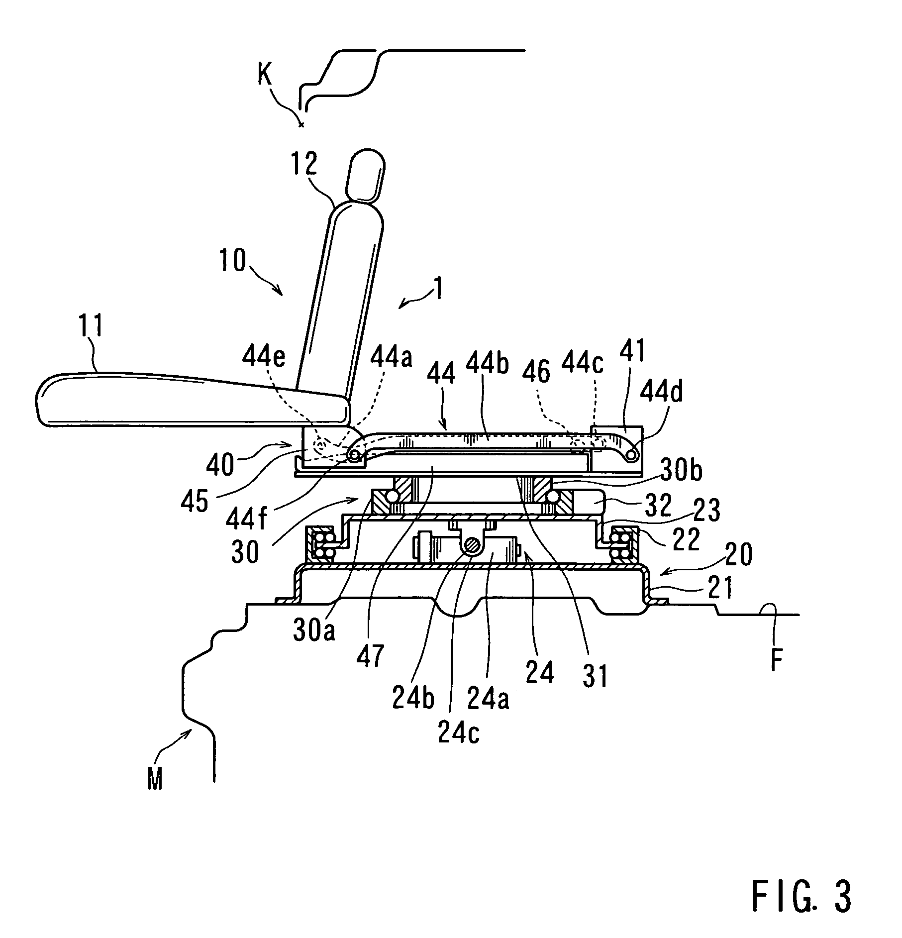
The present invention relates to a vehicle seat moving apparatus that reduces the fluctuation of load on the drive source when the seat moves between a raised position and a lowered position. The technical effect of the invention is to provide a technique that effectively reduces the range of fluctuation of the load on the electric motor when the seat moves. This is achieved by using an ascent / descent guide member that supports the seat raising / lowering arm at a position spaced apart from the rotation center of the arm, and a horizontal guide surface that guides the arm in a predetermined path. The ascent / descent guide member also includes a stopper portion that contacts the arm and restrains further movement of the arm to prevent overrun. The invention smoothly moves the seat and reduces the load on the electric motor, increasing durability of the drive source.

Problems solved by technology

When the range of fluctuation of the load applied to the electric motor is so large, the electric motor may suffer premature deterioration.

Method used


Image

  • Seat moving device for vehicle
  • Seat moving device for vehicle
  • Seat moving device for vehicle

Examples


second embodiment

[0087]Consequently, the second embodiment is provided in order to reduce the raising force acting on the widthwise slide base 41 when the widthwise slide base 41 moves.

[0088]FIG. 12 is a side view of the raising / lowering mechanism 48 for the seat main body 10. FIG. 13 is a rear view of the same. Further, in FIG. 12, the lower link arm 44b, which is not directly pertinent, is omitted, and mainly the upper link arm 44a is shown. As shown in the drawings, in the second embodiment, an auxiliary roller 61 is provided as a horizontal retaining member which directly supports the lower surface of the upper link arm 44a and guides the upper link arm 44a so as to horizontally move the same. The auxiliary roller 61 is attached to the side surface of the cam plate 47 so as to be rotatable at a fixed position. The auxiliary roller 61 is positioned near the boundary between the horizontal guide surface 47a and the inclined guide surface 47b.

[0089]That is, in the second embodiment when the widthw...

third embodiment

[0096]Consequently, the third embodiment is provided in order to prevent broad transmission of the impact that is generated due to prevention of the overrun of the seat main body 10 when the seat main body 10 moves to a lowered position.

[0097]In the third embodiment, a driving device 70 for widthwise sliding, which moves the widthwise slide base 41 (which is not shown in FIGS. 14-16), is equipped with an overrun preventing means. As shown in FIG. 14, the driving device 70 for widthwise sliding is composed of an electric motor 71 as a drive source, a screw shaft 73 rotated by the electric motor 71 via a reduction gear 72, and a movable nut 74 meshing with the screw shaft 73 or other such components. For example, the electric motor 71, the reduction gear 72, and the screw shaft 73, are attached to the side of the widthwise slide base 41, and the movable nut 74 is attached to the rotation base 31 side. The screw shaft 73 is equipped with a stationary nut 75 which serves as a means for ...

first embodiment

[0098]As described with regard to the first embodiment, the stopping of the seat main body 10 at the lowered position, i.e., the stopping of the widthwise slide base 41 at the advance position, is performed by a pulse signal from a limit switch (not shown) or the electric motor 71. However, if there is any abnormality in these components, an overrun occurs.

[0099]FIG. 15 shows a normal stopping condition in which the seat main body 10 is stopped at a predetermined lowered position. In this condition, the movable nut 74 and the stationary nut 75 are opposed to each other with a predetermined interval C therebetween. FIG. 16 shows an overrun condition in which the seat main body 10 is excessively moved over the predetermined lowered position. In this condition, the movable nut 74 and the stationary nut 75 abut each other, thereby limiting the movement of the seat main body 10.

[0100]In this way according to the third embodiment, at the time of overrun the stationary nut 75 fixed to the ...


PUM


Abstract

It is one object of this invention to provide a technique that is effective in diminishing the range of fluctuation of a load applied to a drive source when a seat main body in a vehicle seat moving apparatus is moved between a raised position and a lowered position.For this purpose, this invention provides a vehicle seat moving apparatus constructed as follows. Provided on a rotation base 31, for rotating a seat main body 10 between a position where it faces the front side of the vehicle and a position where it faces a door opening, is a widthwise slide base 41 that moves horizontally in the vehicle width direction while the seat main body 10 faces the door opening. The seat main body 10 is supported by the slide base 41 via four-bar linkage mechanisms 44. Guide rollers 46 are attached to upper link arms 44a of the four-bar linkage mechanisms 44. The guide rollers 46 are placed on cam surfaces of cam plates 47 provided to the rotation base 31. The cam surfaces have continuously extending inclined guide surfaces 47b that guide such that the guide rollers 46 move obliquely upwards when the widthwise slide base 41 moves.

Description

TECHNICAL FIELD[0001]This invention relates to a vehicle seat moving apparatus that makes it possible for, for example, a physically handicapped person, an elderly person or other such persons (hereinafter simply referred to as “occupant”) to easily get in and out of the vehicle.BACKGROUND ART[0002]A conventional technique regarding a vehicle seat moving apparatus of this type is taught, for example, by Japanese Laid-Open Patent Publication No. 9-39622. As shown in FIG. 17, this conventional vehicle seat moving apparatus has a rotation base 102 for rotating a seat main body 101 between a position where it faces the front side of the vehicle and a position where it faces a door opening K, and a slide base 103 is provided to the rotation base 102 so as to be horizontally movable. Further, a seat support base 105 is supported on the slide base 103 via a vertically rotatable four-bar linkage mechanism 104 that is constituted of an upper link arm 104a and a lower link arm 104b. The seat ...

Claims


Application Information

Patent Timeline
Patent Type & Authority Patents(United States)
IPC IPC(8): B60N2/02B60N2/06B60N2/14B60N2/16B60N2/24
CPCB60N2/067B60N2/14B60N2/1625B60N2/245B60N2/06
Inventor IWATANI, MASAMITSUHIJIKATA, TAKAFUKIFUJITA, CHIKANORISUGA, YASUOMIURA, YOSHIYUKIHORIGUCHI, KENJIMURABAYASHI, KENJIYAMADA
Owner TOYOTA SHATAI KK
Learn More