
Protective cap for medical male luer fittings

a protective cap and fitting technology, applied in the direction of caps, liquid handling, transportation and packaging, etc., can solve the problems of increasing equipment complexity, using protective caps with threaded annular members, etc., and achieve the effect of high repeatability and high accuracy

Inactive Publication Date: 2008-01-08
BAXTER ENGLEWOOD
View PDF24 Cites 103 Cited by
  • Summary
  • Abstract
  • Description
  • Claims
  • Application Information

AI Technical Summary

Benefits of technology

[0008]A related objective of the present invention is to provide enhanced methods for the capping / uncapping of male luer fittings having a nozzle and surrounding collar, including automated syringe capping systems.
[0009]Yet a further objective of the present invention is to provide an improved protective cap for maintaining the sterility of and otherwise sealing the nozzle of a male luer fitting having a surrounding collar.
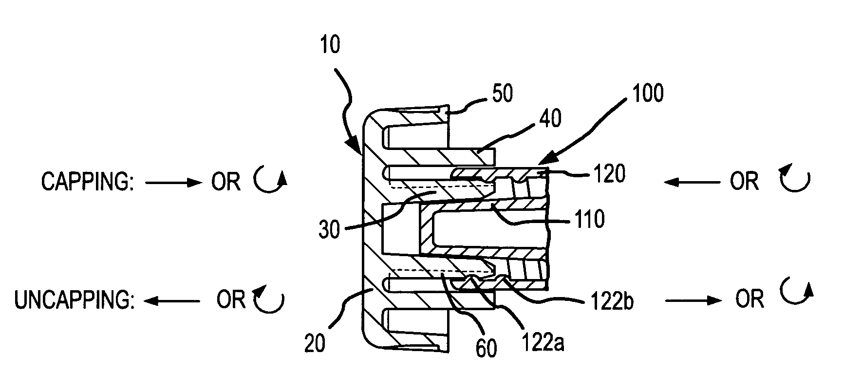
[0031]In conjunction with the inventive method, the advancement and retraction steps may be achieved by rotating at least one of the protective cap and male luer fitting relative to the other. During advancement / retraction, such rotation causes the collar threads of the male luer fitting to engage / disengage the depressible member(s) across spaced segments thereof in corresponding relation to the spacing between the collar threads. Alternatively, advancement and retraction may be achieved via simple linear advancement (e.g. pushing) / retraction (e.g. pulling) of one of the protective cap and male luer fitting relative to the other. Such linear advancement / retraction causes the internal collar threads of the male luer fitting to progressively engage the depressible member(s) along a portion of the length thereof in a distal-to-proximal / proximal-to-distal manner.
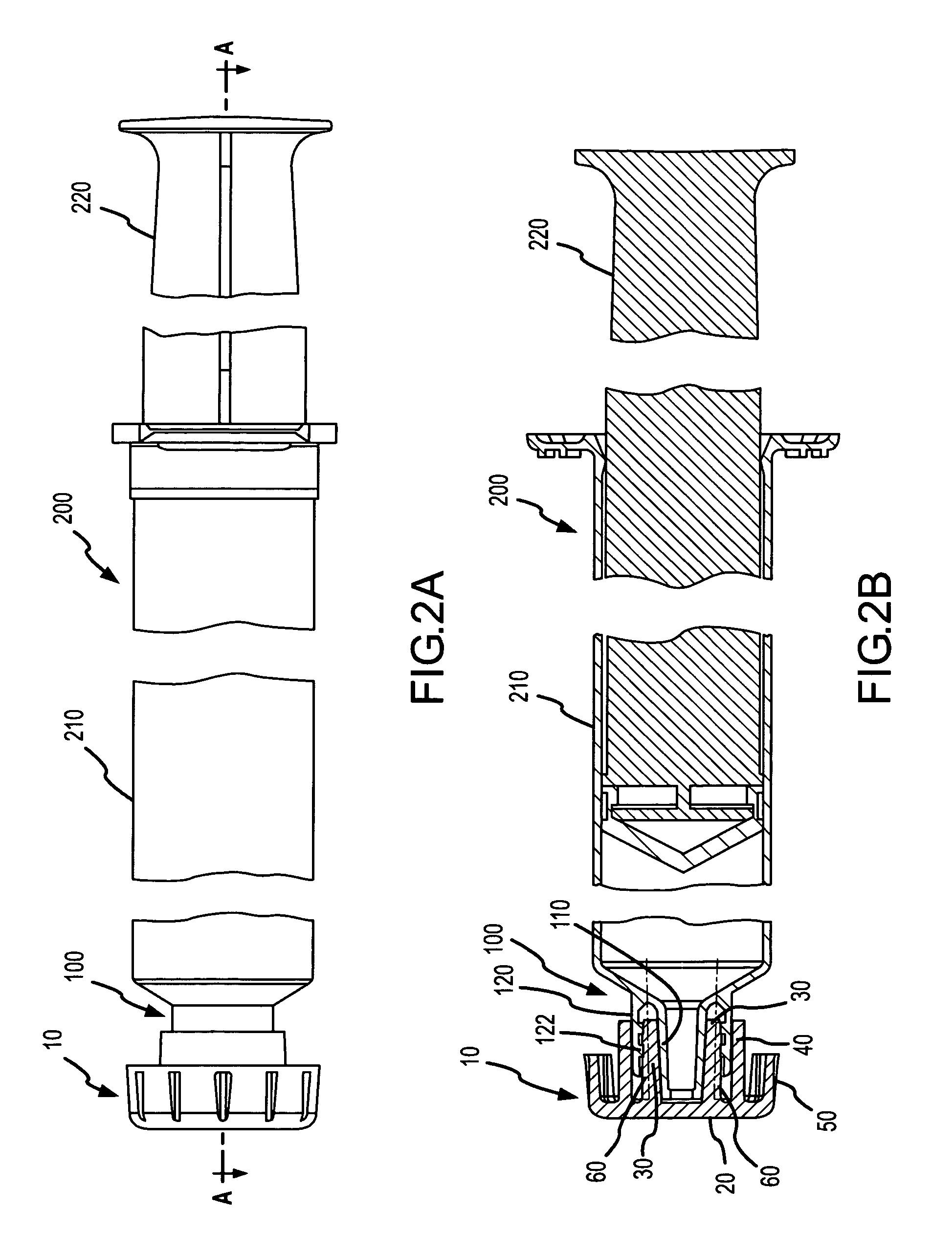
[0032]Of note, the inventive method may be advantageously employed in conjunction with automated processes. In such processes, the protective cap and male luer fitting may be positioned in corresponding holders, wherein at least one of the holders is disposed for driven linear and / or rotational advancement relative to the other. Most preferably, the holder for the protective cap may be linearly retracted and advanced again for automated uncapping and recapping. As may be appreciated, automation is significantly simplified by the capability to achieve reliable and repeatable capping / uncapping via linear advancement / retraction.
[0034]In conjunction with such system automated syringe filling may occur at a first location (e.g. at a production facility of a pharmacy of a medical care site). For example, a disposable syringe capped with a protective cap of the present invention may be positioned in a first holder. Then, a second holder may be advanced toward the first holder to engage and capture the protective cap. Upon linear retraction of the second holder, the protective cap is automatically removed, or pulled, from the disposable syringe. Then, the syringe may be automatically filled with a medical liquid (e.g. by flowing the medical liquid under pressure through the nozzle of a male luer fitting into the syringe). Thereafter, the second holder may be positioned to align the protective cap relative to the male luer fitting of the filled syringe. Finally, the second holder may be linearly advanced to position, or push, the protective cap on the filled syringe to a predetermined desired location with high and repeatable accuracy.

Problems solved by technology

Further, in that regard, in automated systems for capping / uncapping collared male luer fittings (e.g. in conjunction with the automated assembly and / or filling of a disposable syringe), the utilization of protective caps having threaded annular members may increase equipment complexity since each protective cap and / or interfacing male luer fitting must be supportably disposed for both automated linear and rotational movement.

Method used


Image

  • Protective cap for medical male luer fittings
  • Protective cap for medical male luer fittings
  • Protective cap for medical male luer fittings

Examples


Embodiment Construction

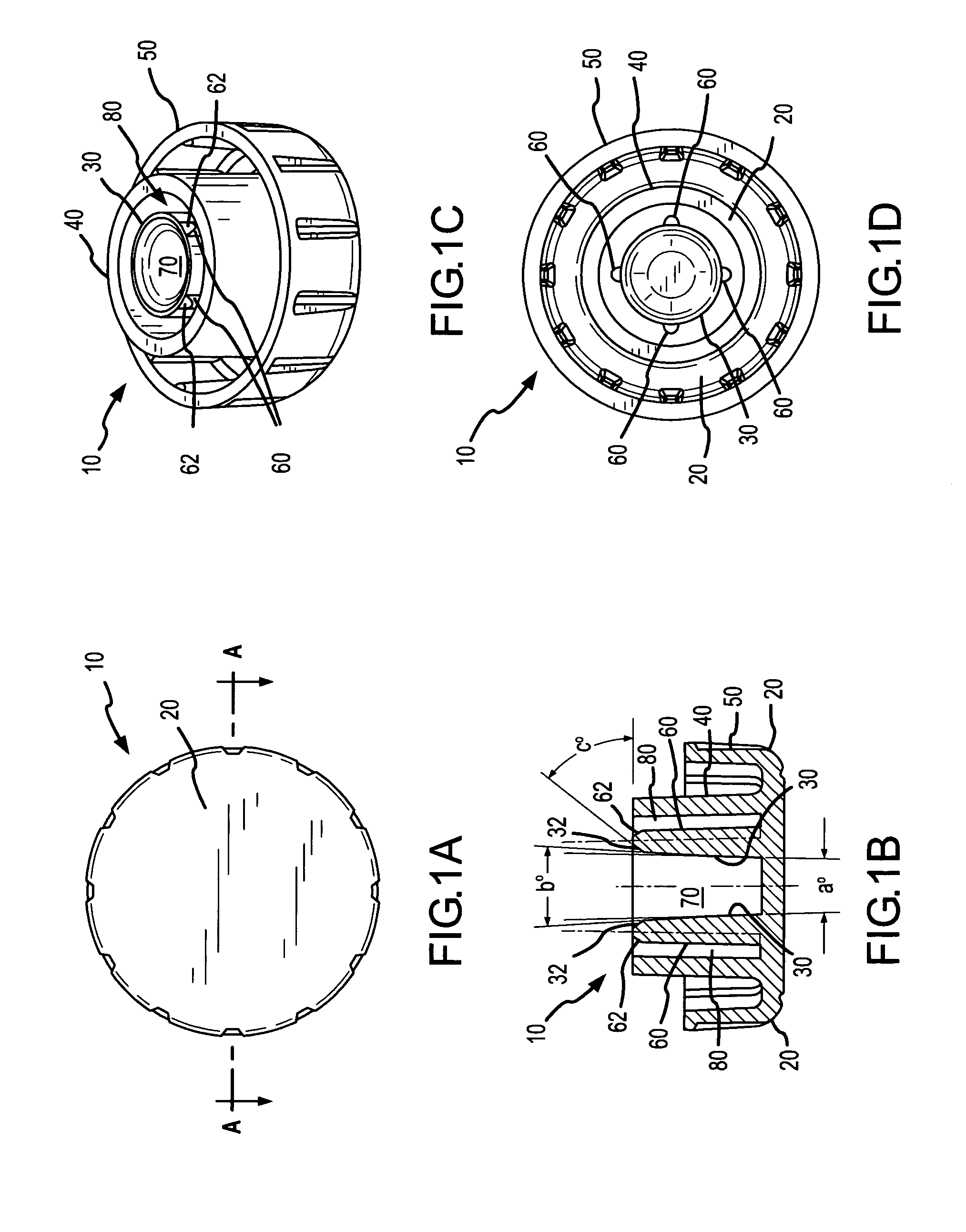
[0044]FIGS. 1A-1D illustrate one embodiment of a protective cap 10 comprising the present invention. As shown, protective cap 10 comprises an end wall 20 having annular members 30, 40 and 50 extending therefrom. The annular members 30, 40 and 50 are concentrically positioned about a center axis of the protective cap 10. Inner and intermediate annular members 30 and 40, respectively, may extend substantially the same distance from the end wall 20 to their distal ends, while outer annular member 50 extends a lesser distance from the end wall 20. As best shown by FIG. 1B, inner annular member 30 defines a generally cylindrical center slot 70, and the inner and intermediate annular members 30 and 40, respectively, define an annular slot 80 therebetween. Slots 70 and 80 are sized and otherwise located for the receipt of the nozzle and collar of a male luer fitting. For common applications, the annular slot 80 may have a maximum cross-width of between about 0.040 and 0.050 inches (e.g. as...


PUM


Abstract

An improved protective cap and method for capping medical male luer fittings is provided. The protective cap may include inner and intermediate annular members extending from an end wall and defining a slot therebetween. At least one and preferably a plurality of depressible members project from an outer surface of the inner annular member, wherein the depressible member(s) conforms to the internal threads of a male luer fitting upon interconnection. For such purposes, the depressible member(s) may comprise a resilient material, e.g. most preferably having a modulus of elasticity of between about 5000 psi and 20000 psi. Each depressible member may be of an arcuate configuration in cross-section to present a convex surface for depressible engagement by the collar of a male luer fitting when positioned in the annular slot. The protective cap may be readily employed in automated capping / uncapping procedures via direct linear advancement / retraction relative to a male luer fitting. The protective cap may also be readily rotated onto and off of a male luer fitting. The protective cap and associated methodologies are particularly apt for use in connection with syringes, including automated procedures for pre-filling disposable syringes with medical liquids.

Description

FIELD OF THE INVENTION[0001]The present invention relates to the capping and uncapping of medical male luer fittings utilized in medical liquid transfusion, infusion or injection applications. The protective cap is particularly apt for use in conjunction with disposable syringes and automated syringe capping systems.BACKGROUND OF THE INVENTION[0002]Male luer fittings are utilized in a wide variety of medical liquid transfusion, infusion and injection applications. By way of example, ISO standards 594-1 and 594-2 (i.e. as published by the International Organization for Standardization) set forth specifications for conventional male luer fittings.[0003]In one primary use, male luer fittings are provided on disposable syringes for selectively receiving a hub from which a needle projects. The hub is sized to slidably and sealably receive a complimentary nozzle of the male luer fitting. Typically, to enhance the reliability of interconnection, the male luer fitting includes an annular co...

Claims


Application Information

Patent Timeline
IPC IPC(8): A61M5/32A61M5/31A61M5/34
CPCA61M5/3134A61M5/347A61M2005/3104
Inventor RANALLETTA, JOSEPH V.
Owner BAXTER ENGLEWOOD
Learn More