Skeletal topography imaging radar for unique individual identification

Inactive Publication Date: 2008-01-08
FLOM LEONARD +1
View PDF8 Cites 71 Cited by
  • Summary
  • Abstract
  • Description
  • Claims
  • Application Information

AI Technical Summary

Benefits of technology

[0011]It is a further object of the present invention to provide an imaging radar system that is compact and safe for use in mapping the topography of the human skeleton and portions thereof.

Problems solved by technology

However, imaging radar uses microwaves to generate the image rather than visible light.
Further, because the radar wavelengths are much longer than those of visible or infrared light, imaging radar systems can often capture images through cloudy and dusty conditions while visible and infrared instruments cannot.

Method used


Image

  • Skeletal topography imaging radar for unique individual identification
  • Skeletal topography imaging radar for unique individual identification
  • Skeletal topography imaging radar for unique individual identification

Examples


Embodiment Construction

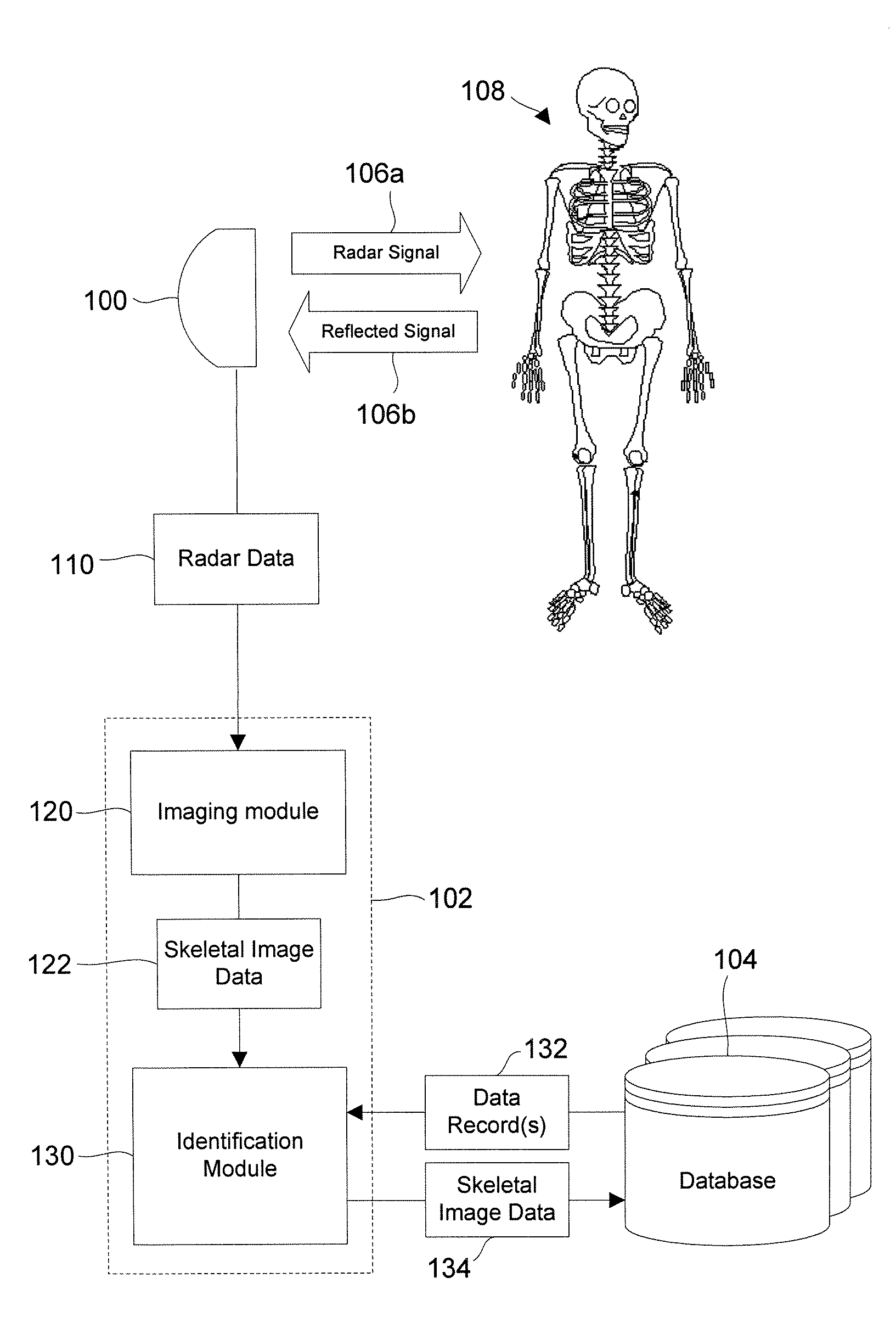
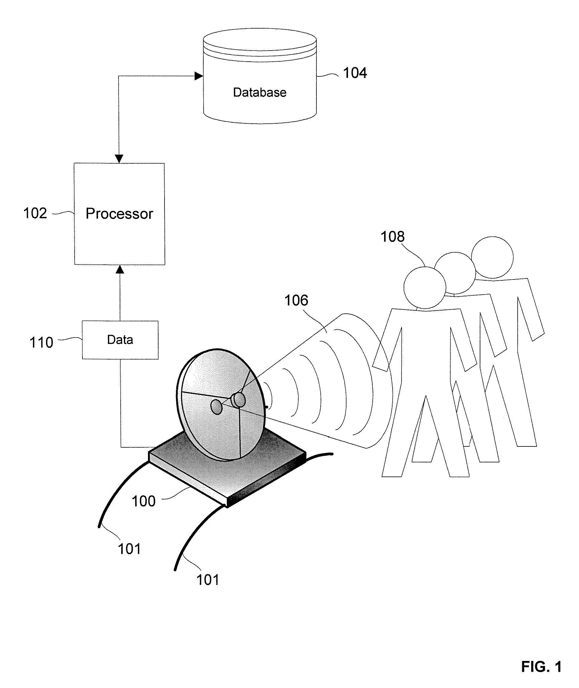
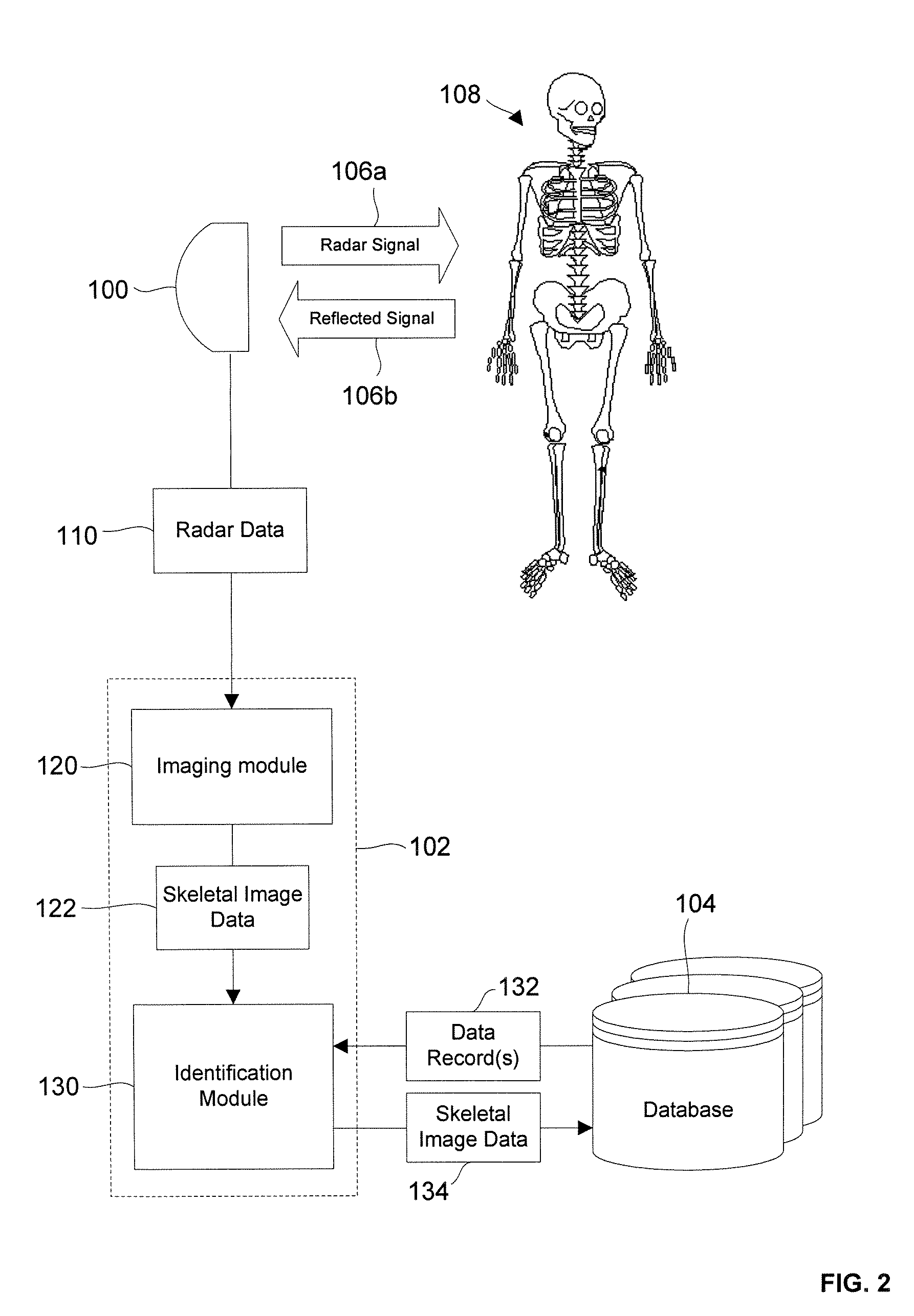
[0020]FIG. 1 shows an exemplary imaging radar system for identifying individuals according to the present invention. The system includes an imaging radar 100. The imaging radar 100 may be any imaging radar. For example, the imaging radar 100 may be a Synthetic Aperture Radar (“SAR”). In one embodiment, the imaging radar 100 is located at a ground location (either active or fixed). For example, the imaging radar 100 may be at a security checkpoint (e.g., airport, secure facility, etc.). In other embodiments, the imaging radar 100 is an active radar mounted on an aerial platform such as a satellite or an aircraft. The radar may also be mounted on a track and / or rail system 101 (e.g., on the ground, a floor, and / or a roof) along which it can be moved rapidly.

[0021]The exemplary embodiment shown in FIG. 1 further includes a processor 102. The processor 102 may be any device, system or part thereof that controls at least one operation and / or executes software applications. The processor ...


PUM


Abstract

A system for identifying an individual, including an imaging radar for receiving radar data pertaining to at least a portion of a skeleton of at least one individual, an imaging module for generating at least one skeletal image of the at least one individual based on the radar data, at least one database including a plurality of skeletal data pertaining to a plurality of individuals, an identification module for comparing the at least one skeletal image with the plurality of skeletal data to determine a match.

Description

CROSS-REFERENCE TO RELATED APPLICATIONS[0001]This application claims priority benefits under 35 § U.S.C. 119(e) of the U.S. Provisional Application No. 60 / 753,540, filed on Dec. 22, 2005.FIELD OF THE INVENTION[0002]The invention relates to imaging radar systems, and more specifically to a skeletal imaging radar system for identifying individual persons or animals.BACKGROUND OF THE INVENTION[0003]Imaging radars are known in the art, e.g., for use in environmental monitoring and earth-resource mapping. Typically imaging radars are active systems which send pulses and receive radial reflected radiation after striking a material in its path. The radiation received is comprised of both radiometry information (e.g., the intensity of the reflection energy) and spatial information (e.g., the distance and the azimuth of the material relative to the sensor). An imaging radar works like a flash camera in that it provides radiation to one or more surfaces and generates an image based on radiati...

Claims


Application Information

Patent Timeline
Patent Type & Authority Patents(United States)
IPC IPC(8): G01S13/00
CPCG01S7/412G01S13/89
Inventor FLOM, LEONARDALMOG, OPHIR
Owner FLOM LEONARD
Why Eureka
Try Eureka