

Image pickup apparatus for processing an image signal by using memory
- Summary
- Abstract
- Description
- Claims
- Application Information
AI Technical Summary
Benefits of technology
Problems solved by technology
Method used
Image

Examples
Embodiment Construction
[0024]Hereinafter, explanation will be made of an embodiment of the present invention with reference to the drawings.
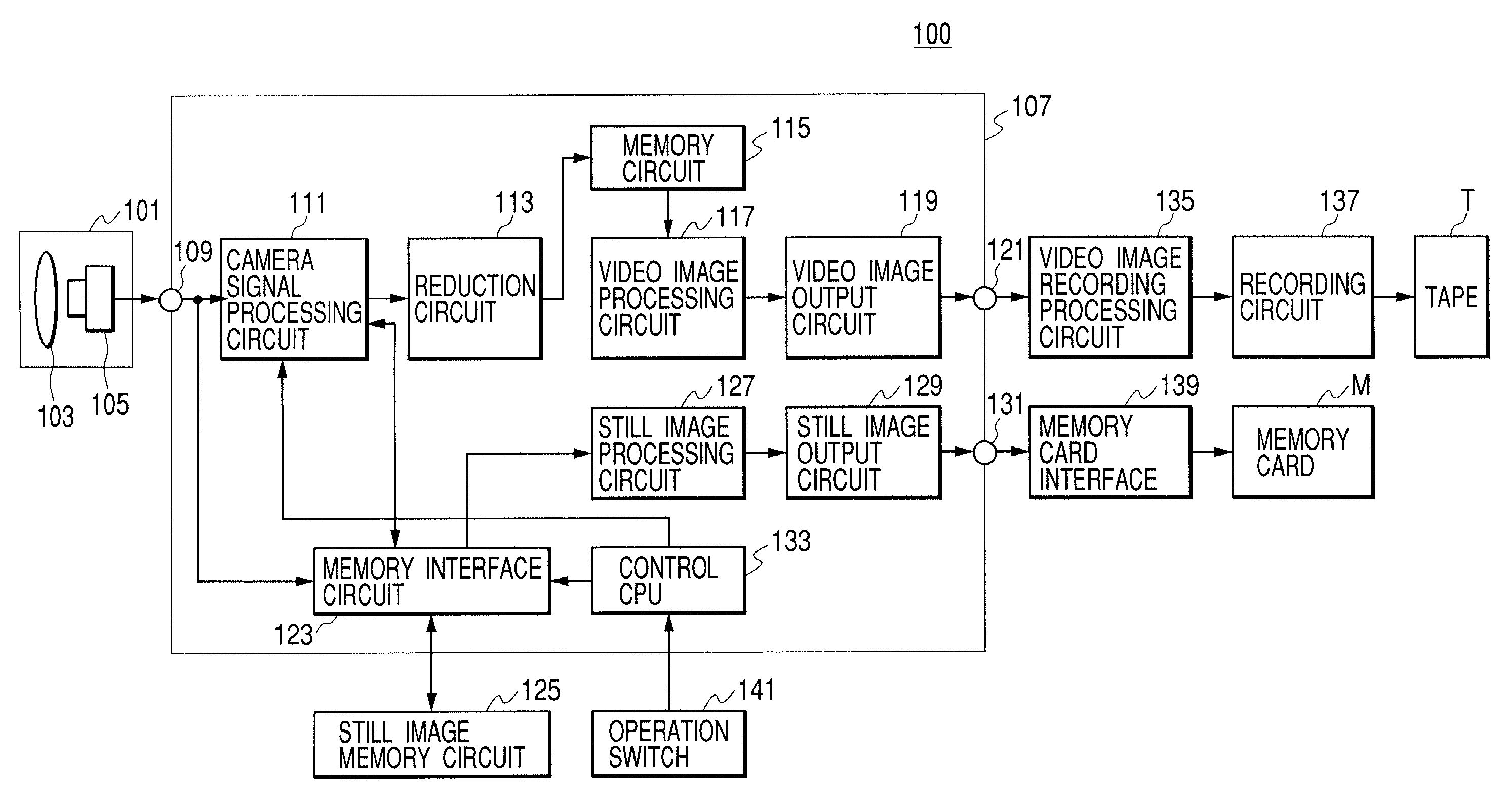
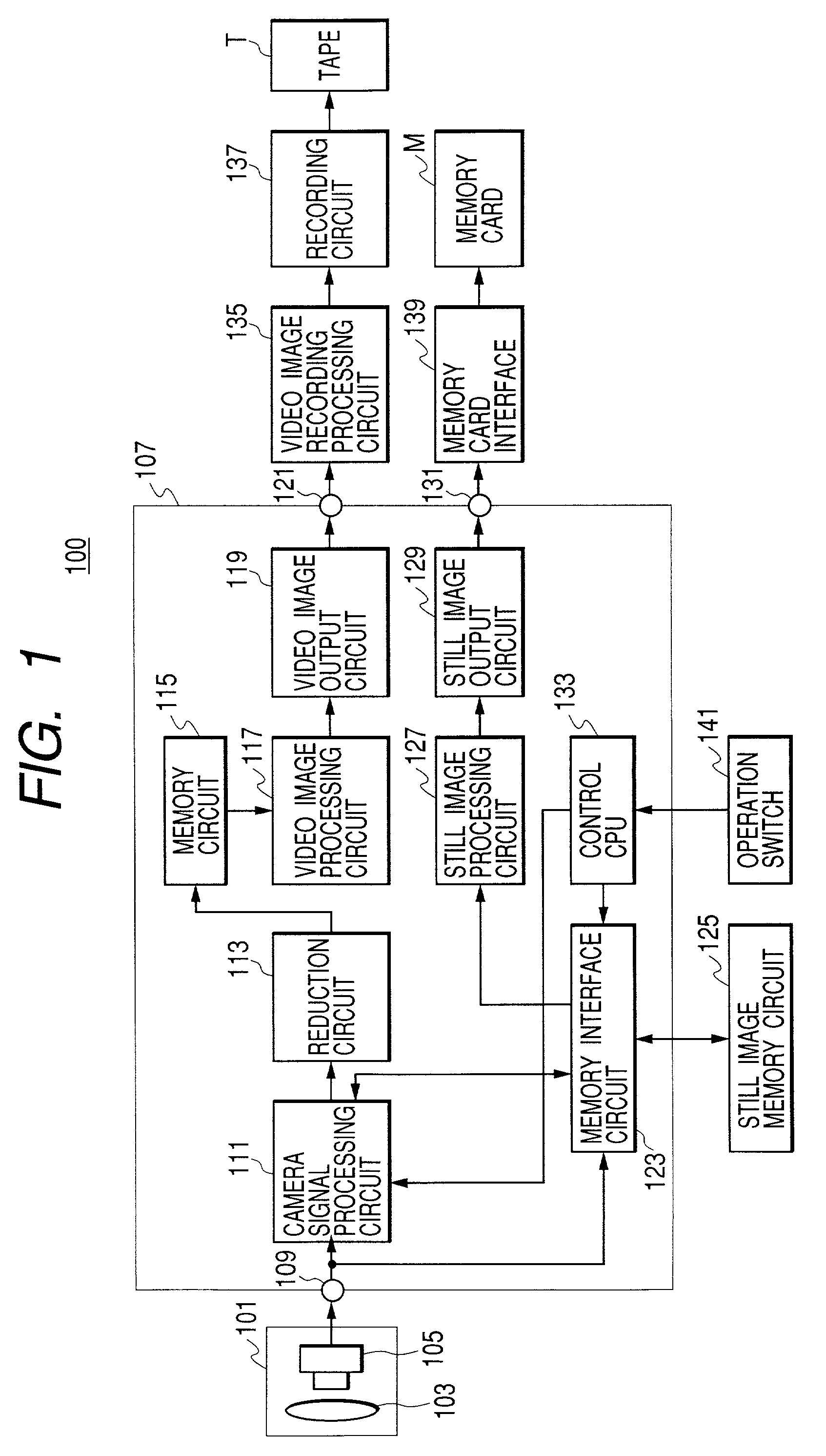
[0025]FIG. 1 is a block diagram showing a construction of a digital VTR 100 which is integrated into a camera to which the present invention is applied. The digital VTR of the present invention is provided with a card slot to which a memory card is mounted, and has a moving image mode for recording moving image data onto a magnetic tape, and a still image mode for recording still image data onto the memory card. Explanation will be made of operations in the moving image mode first.
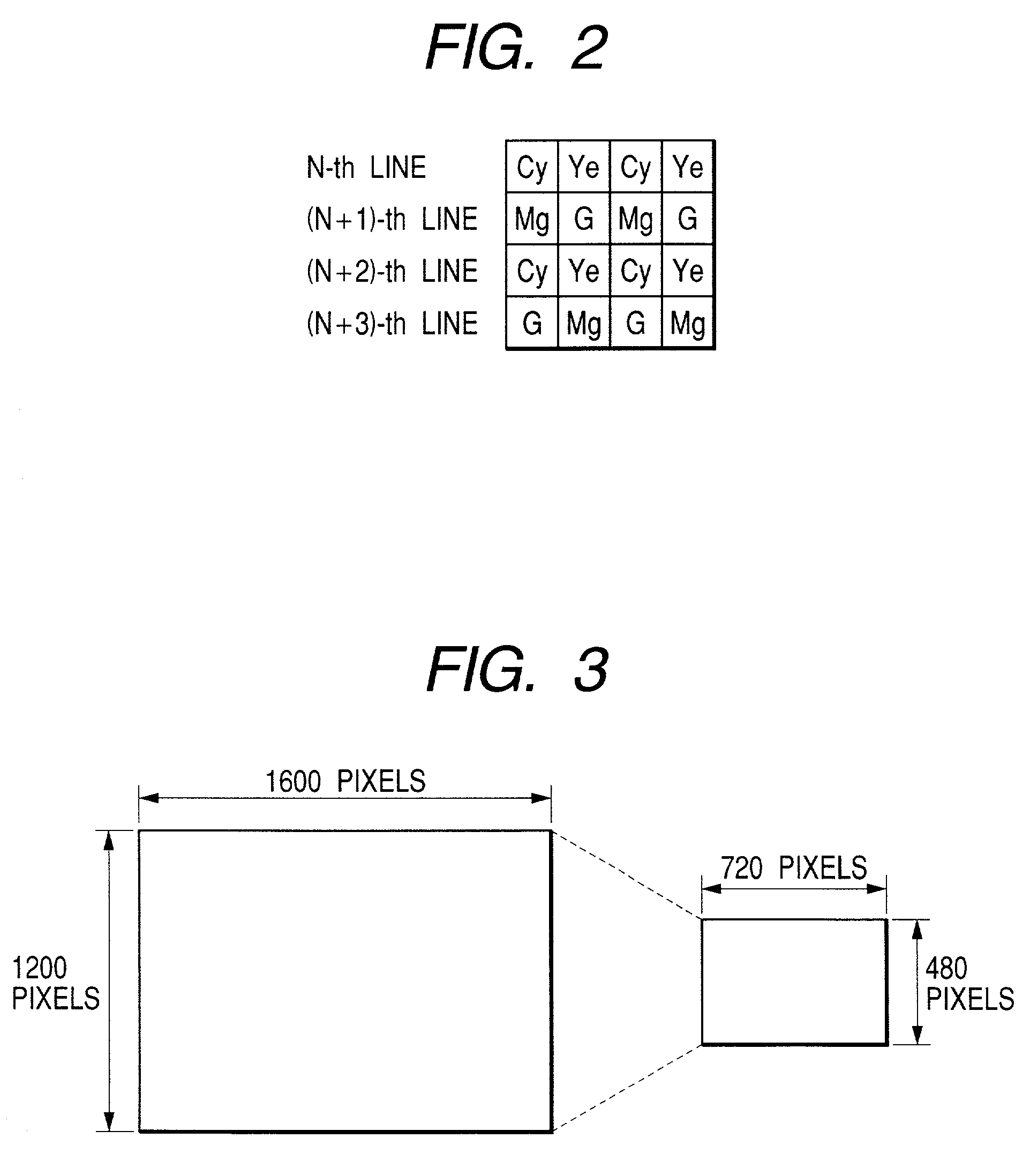
[0026]In FIG. 1, reference numeral 101 is an image pickup circuit, which is comprised of an optical system 103 including a lens, a diaphragm and the like; and an image pickup element 105 including a CCD, a drive circuit and A / D converter therefor and the like. In the apparatus in FIG. 1, the image pickup device is a single CCD arranged with a general complimentary color filter, and the numbe...
PUM
 Abstract
Description
Claims
Application Information