Method and device for attenuating the motion of hydraulic cylinders of mobile work machinery

a technology of mobile work machinery and hydraulic cylinders, which is applied in the direction of electric variable regulation, position/direction control, instruments, etc., can solve the problems of affecting the integrity of the cylinder housing, and affecting the operation of the machinery. achieve the effect of improving the state of the ar

Inactive Publication Date: 2008-01-15
LIEBHERR FRANCE
View PDF11 Cites 85 Cited by
  • Summary
  • Abstract
  • Description
  • Claims
  • Application Information

AI Technical Summary

Benefits of technology

[0008]It is thus the object of the present invention to create an improved method and an improved device for attenuating the motion of hydraulic cylinders of the type described in the introduction, to avoid the disadvantages of the state of the art, and to advantageously improve said state of the art.

Problems solved by technology

Due to these deviations of parameters relating to the geometry and the fluid, there is a good likelihood that either the banking-up pressure is insufficient to activate the control devices, or that the banking-up pressure increases to such an extent that the integrity of the cylinder housing is endangered.
This results in the motion being decelerated, depending on the switching speed of the directional control valve.
However, with this solution, stopping regularly takes place either too early or too late.
This means that either the kinematics are not completely utilised, or that the mechanical limit stop of the hydraulic cylinder is still reached at excessive speed.
Furthermore, during uncontrolled switching off, pressure peaks occur on the outflow side, while the inflow side is filled incompletely, with both of these occurrences leading to increased loads on the lines and hydraulic components.

Method used


Image

  • Method and device for attenuating the motion of hydraulic cylinders of mobile work machinery
  • Method and device for attenuating the motion of hydraulic cylinders of mobile work machinery
  • Method and device for attenuating the motion of hydraulic cylinders of mobile work machinery

Examples


Embodiment Construction

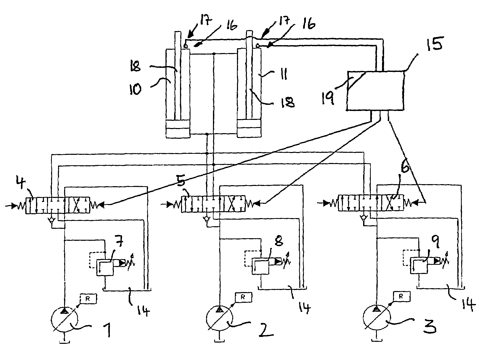
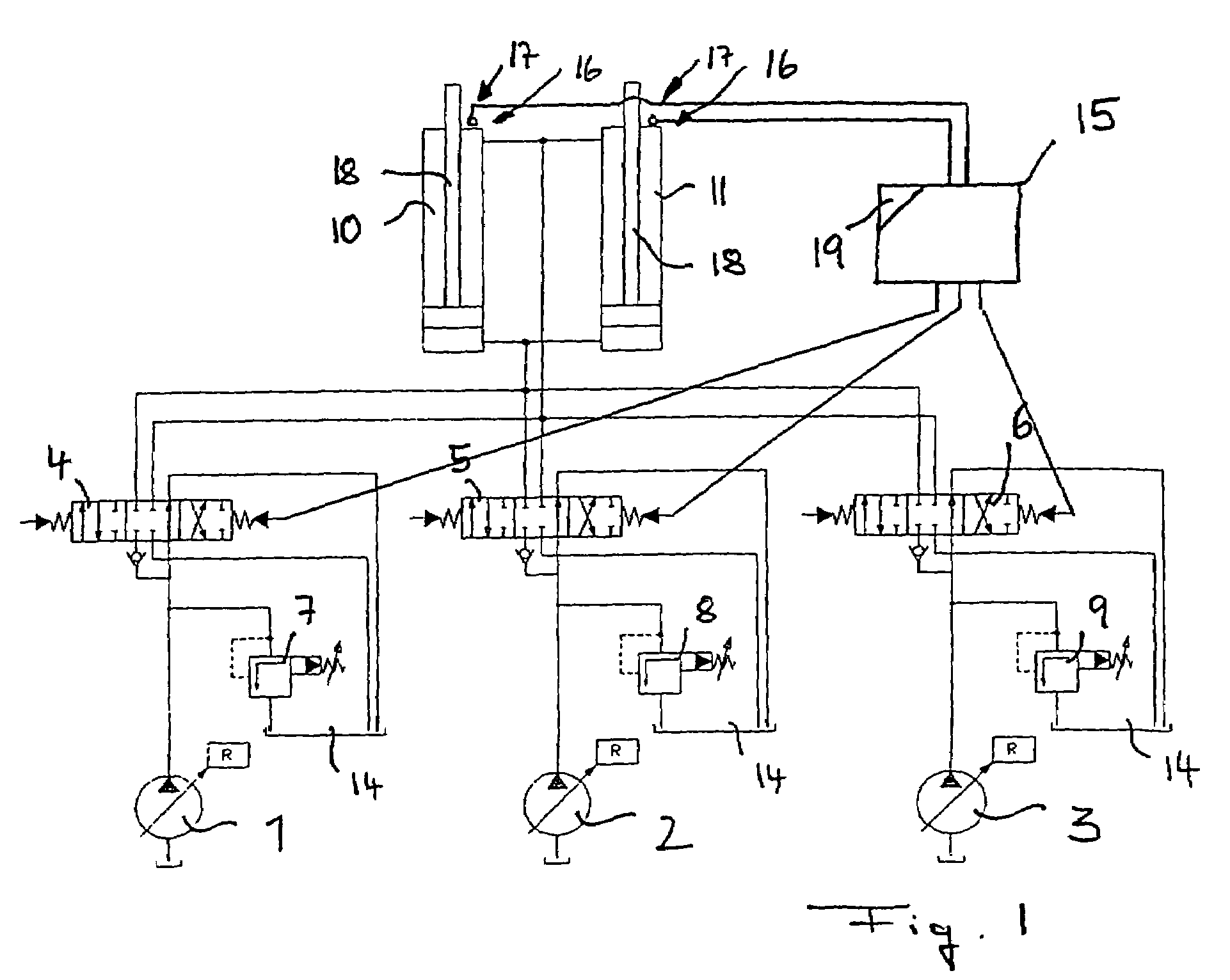
[0029]As shown in FIG. 1, the hydraulic cylinders 10 and 11, which for example can be the lifting cylinders of a hydraulic excavator, are driven by a hydraulic drive which comprises three hydraulic pumps 1, 2 and 3, each of which can be regulated by way of a regulator R. The three hydraulic pumps 1, 2 and 3 are connected to the hydraulic cylinders 10 and 11, each by way of a directional control valve 4, 5 and 6, with said hydraulic cylinders 10 and 11 also being switched in parallel in relation to each other. By means of the directional control valves 4, 5 and 6, the inflows to, and the outflows from, the hydraulic cylinders 10 and 11 can be cut off and shut off from the respective pumps 1, 2 and 3 in a way which is known per se, or a flow connection to the pump can be established, wherein the direction of flow is reversible so that the hydraulic cylinders can be extended and retracted. Upstream of the directional control valves 4, 5 and 6, the pressure lines emanating from the pump...


PUM


Abstract

The present invention relates to a method for attenuating the motion of hydraulic cylinders of mobile work machinery, in particular of hydraulic excavators, in which prior to the hydraulic cylinder reaching one of the limits of travel, its motion speed is reduced, and the hydraulic cylinder is moved to the respective limit of travel at reduced speed; wherein for the purpose of reducing the speed, the inflow to, and/or the outflow from, the hydraulic cylinder are/is throttled by a flow control device. According to the invention, the method is characterized by, prior to the respective limit of travel being reached, the motion speed of the hydraulic cylinder is registered, and the point in time when throttling commences is changed depending on the registered motion speed. Furthermore, the present invention relates to a device for attenuating the motion of hydraulic cylinders of mobile work machinery, in particular of hydraulic excavators, a position registering device for registering a preliminary limit position of the hydraulic cylinder, a control device for throttling the inflow and/or outflow of the hydraulic cylinder, and a control device for controlling the flow control device when the preliminary limit position is reached. According the invention, the device has a speed registering device for registering the motion speed of the hydraulic cylinder when the preliminary limit position is reached, and the control device has a delay device for delaying driving the flow control device, depending on the recorded motion speed.

Description

BACKGROUND OF THE INVENTION[0001]The present invention relates to a method as well as to a device for attenuating the motion of hydraulic cylinders of mobile work machinery, in particular of hydraulic excavators, wherein, by means of a position registering device, reaching of a preliminary limit position of the hydraulic cylinder is registered; prior to the limits of travel of the hydraulic cylinder being reached, its motion speed is reduced; and the hydraulic cylinder is moved to the respective limit of travel only at reduced speed. To this effect a flow control device for throttling the inflow to, and / or the outflow from, the hydraulic cylinder is provided, with said throttling being correspondingly driven by a control device when the preliminary limit position is reached, so as to throttle the flow quantity which flows into, or out of, said hydraulic cylinder.[0002]The motion attenuation or limit of travel switch-off of hydraulic cylinders ensures that the speed of the hydraulic ...

Claims


Application Information

Patent Timeline
Patent Type & Authority Patents(United States)
IPC IPC(8): E02F5/02G05F1/02E02F9/22F15B15/22F15B11/04F15B11/048F15B21/02
CPCE02F9/2214F15B11/048F15B2211/20546F15B2211/20576F15B2211/30525F15B2211/31588F15B2211/327F15B2211/6336F15B2211/665F15B2211/7053F15B2211/7128F15B2211/715F15B2211/755F15B21/02
Inventor HELBLING, FRANKKOSSMANN, GERHARD
Owner LIEBHERR FRANCE
Why Eureka
Try Eureka