Steer by brake control system

a technology of brake control system and steering wheel, which is applied in the direction of steering initiation, instruments, vessel construction, etc., can solve the problems of difficult to establish or predict the turning radius, costly four-wheel steering system, etc., and achieve the effect of constant reduction of the turn radius of the vehicl

Active Publication Date: 2008-01-15
KELSEY HAYES CO
View PDF8 Cites 36 Cited by
  • Summary
  • Abstract
  • Description
  • Claims
  • Application Information

AI Technical Summary

Benefits of technology

[0009]The present invention has the advantage of reducing the turn radius of a vehicle when making a slow turn maneuver by applying a braking force to a respective inside vehicle wheel. The present invention further applies a control speed algorithm for maintaining a constant speed through the turn so that a constant reduced turn radius may be maintained without a driver having to manipulate between the accelerator pedal and the brake pedal.

Problems solved by technology
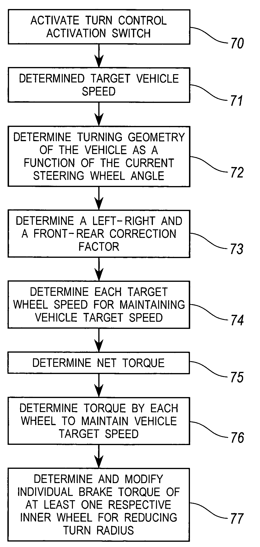
However, such four-wheel steerable systems are costly since additional hardware is required to allow the rear wheels to become steerable.
However, utilizing braking systems where the speed is varying during the braking process makes it difficult to establish or predict the turning radius.

Method used


Image

  • Steer by brake control system
  • Steer by brake control system
  • Steer by brake control system

Examples


third embodiment

[0028]For an all wheel drive system (such as for the third embodiment, as illustrated infra in FIG. 7) making a left turn utilizing SBB and CSC controls, the torque exerted on the each of the vehicle wheels are represented by the following formula:

[0029]T1=lim⁡(0,x,Tmax),where⁢⁢x=Tbrk_CSC-Tbrk_SBB4,(10)T2=lim⁡(0,y,Tmax),where⁢⁢y=T1+Tbrk_SBB2,(11)

T3=T1,   (12)

T4=T2,   (13)

where T1 is a brake torque request on an outside front wheel, where T2 is a brake torque request on an inside front wheel, where T3 is a brake torque request on an outside rear wheel, where T4 is a brake torque request on an inside rear wheel, where Tmax a maximum braking torque achievable on each vehicle wheel, where Tbrk—SBB is an available braking torque for a respective steering wheel angle, and where Tbrk—CSC is a total braking torque for maintaining a constant target vehicle speed.

[0030]FIG. 4 illustrates a graph for a respective vehicle for applying a braking torque Tbrk—SBB to a respective inner wheel of a v...

second embodiment

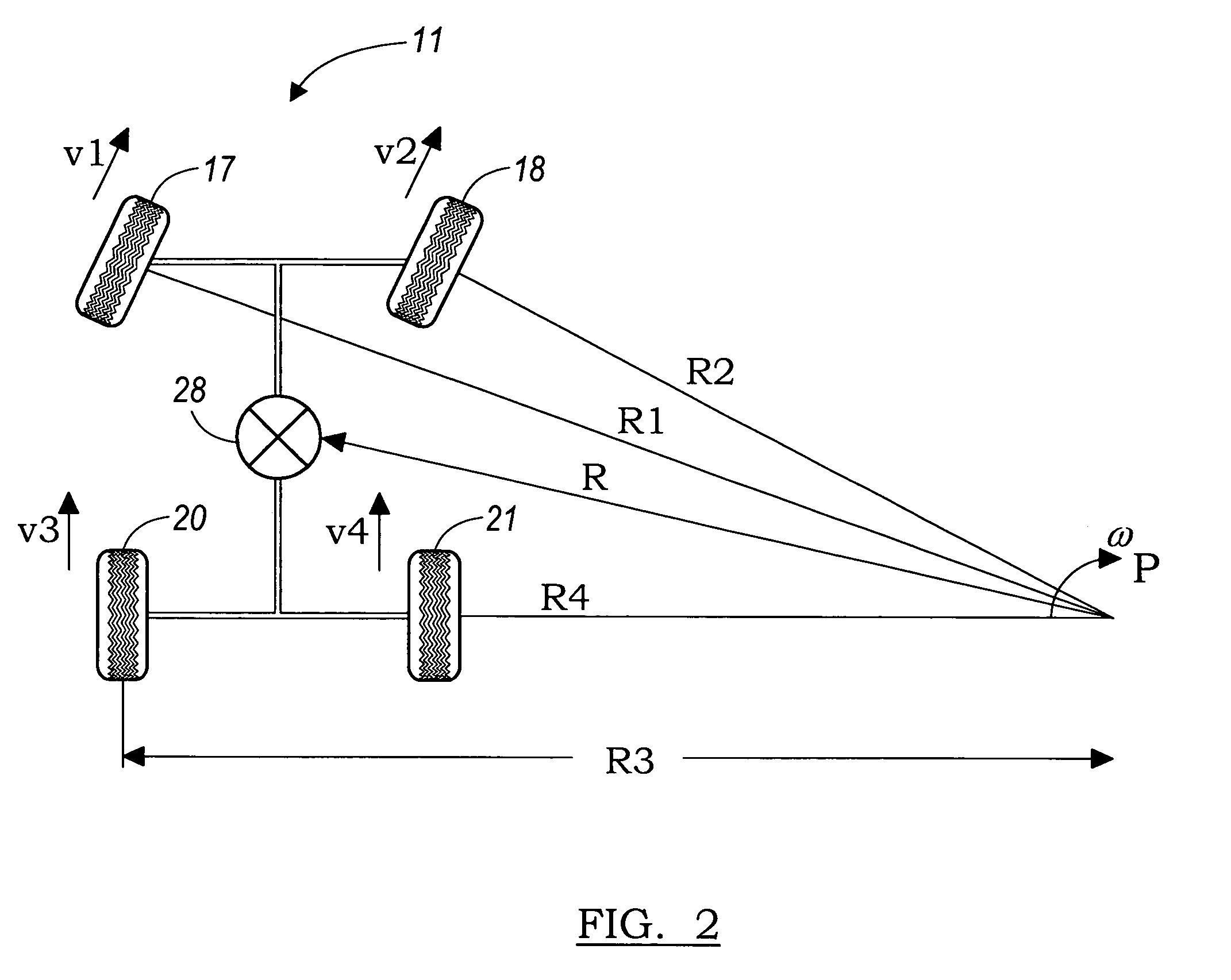
[0033]FIG. 6 illustrates a diagram showing the turning geometry for a rear wheel drive vehicle 31 according to the present invention. As discussed above, the vehicle 11 has a turn radius R about a center point P for a particular steering wheel angle θSWA without special brake force applied, this geometry that generates a TCP 39. An additional braking torque is applied to the front inside wheel 21 as the vehicle travels at a vehicle target velocity vT while at a particular steering wheel angle θSWA. The amount of additional braking torque applied is a function of the vehicle target velocity vT and the steering wheel angle θSWA. This additional braking torque applied to the rear inside wheel 21 will cause the vehicle to change from an initial turn radius R changes to a brake assisted turn radius R′ with a corresponding change in the center turning point from the initial turning center point P to brake assisted turn radius point P′. The turning radius of the vehicle 31 is reduced, even...


PUM


Abstract

A turn control system is provided having four wheels and a steering wheel that controls the vehicle steering. A steering wheel angle sensor senses an angle of rotation of the steering wheel. An acceleration sensing device senses an acceleration demand. A wheel speed sensing device senses a wheel speed for each of the four wheels. A turn control activation switch enables the turn control system and shifts a vehicle transmission to one of a low or reverse operating gear. A brake control module calculates a target vehicle speed, a vehicle turning geometry, and target wheel speeds. A braking torque command signal is generated for modulating the brake torque. An engine torque command signal is generated for modulating an engine torque for producing the target vehicle speed. A respective additional braking torque is applied to at least one of the wheels for reducing the vehicle turning radius while maintaining the vehicle target speed.

Description

CROSS REFERENCE TO RELATED APPLICATIONS[0001]Not Applicable.STATEMENT REGARDING FEDERALLY SPONSORED RESEARCH[0002]Not Applicable.BACKGROUND OF THE INVENTION[0003]1. Field of the Invention[0004]The present invention relates in general to steering by braking systems, and more specifically, to steering by braking utilizing a constant speed velocity control system.[0005]2. Description of the Related Art[0006]Conventional steering systems typically include a steering wheel coupled to a steering column input shaft that is mechanically coupled to a rack in a rack and pinion steering system. The rack and pinion steering system receives the steering input command from the steering wheel for providing a pivoting force on the steerable wheels. Typically the front wheels of a vehicle are steerable whereas the rear wheels are not.[0007]The conventional steering system will have a maximum steering wheel angle which, given a respective speed at which he vehicle is traveling, will produce a respect...

Claims


Application Information

Patent Timeline
Patent Type & Authority Patents(United States)
IPC IPC(8): B60T8/60
CPCB60T8/1755B60T8/1769B60W10/06B60W10/11B60W10/184B62D11/003B62D11/24B60T2260/04B60W2520/28B60W2540/10B60W2540/18
Inventor SUN, QIONGSCHIEB, ERICWEBER, DAVID W.LUBISCHER, FRANK
Owner KELSEY HAYES CO
Why Eureka
Try Eureka