Hydraulic control circuit for a variator

a control circuit and variator technology, applied in the direction of friction gearings, gearing elements, gearings, etc., can solve the problems of large energy loss, variator failure, and excessively high traction coefficient in energy terms

Active Publication Date: 2008-01-15
ALLISON TRANSMISSION INC
View PDF9 Cites 44 Cited by
  • Summary
  • Abstract
  • Description
  • Claims
  • Application Information

AI Technical Summary

Benefits of technology

[0019]In a preferred embodiment the effect of the adjustment means is to reduce the end load pressure so that in the event of inaction of the adjustment means the end load pressure is increased.

Problems solved by technology

An excessively low traction coefficient, corresponding to an unnecessarily high end load and hence high normal force, gives rise to large energy losses at the roller / disc interface and so is inefficient.
An excessively high traction coefficient is also inefficient in energy terms and can lead to variator failure, excessive slip at the roller / disc interface allowing the roller to move, rapidly in some situations, away from its proper position.
Slip losses increase as the degree of slip increases.
However energy losses due to spin are affected by the magnitude of the normal force and hence are related to the traction coefficient.
However such systems are subject to problems.
In some arrangements poor pressure response, in particular a time lag in matching the variator end load to the roller reaction force, has been found to occur.
In conjunction with flow restrictions in the hydraulics, the result can be a significant time lag between the reaction pressure and the end load pressure and hence a transient mismatch between the end load and reaction forces.
In extreme cases there is an associated risk of variator failure.
The additional problem of time lag in adjustment of the end load is not addressed.
Additionally it is believed that there would be severe difficulties in creating a practical implementation of the circuit proposed in this patent, particularly in providing a pulse width modulated valve capable of carrying out the required function.
However this approach does not address the problem of end load time lag and complicates the control of the variator rollers.

Method used


Image

  • Hydraulic control circuit for a variator
  • Hydraulic control circuit for a variator
  • Hydraulic control circuit for a variator

Examples


Embodiment Construction

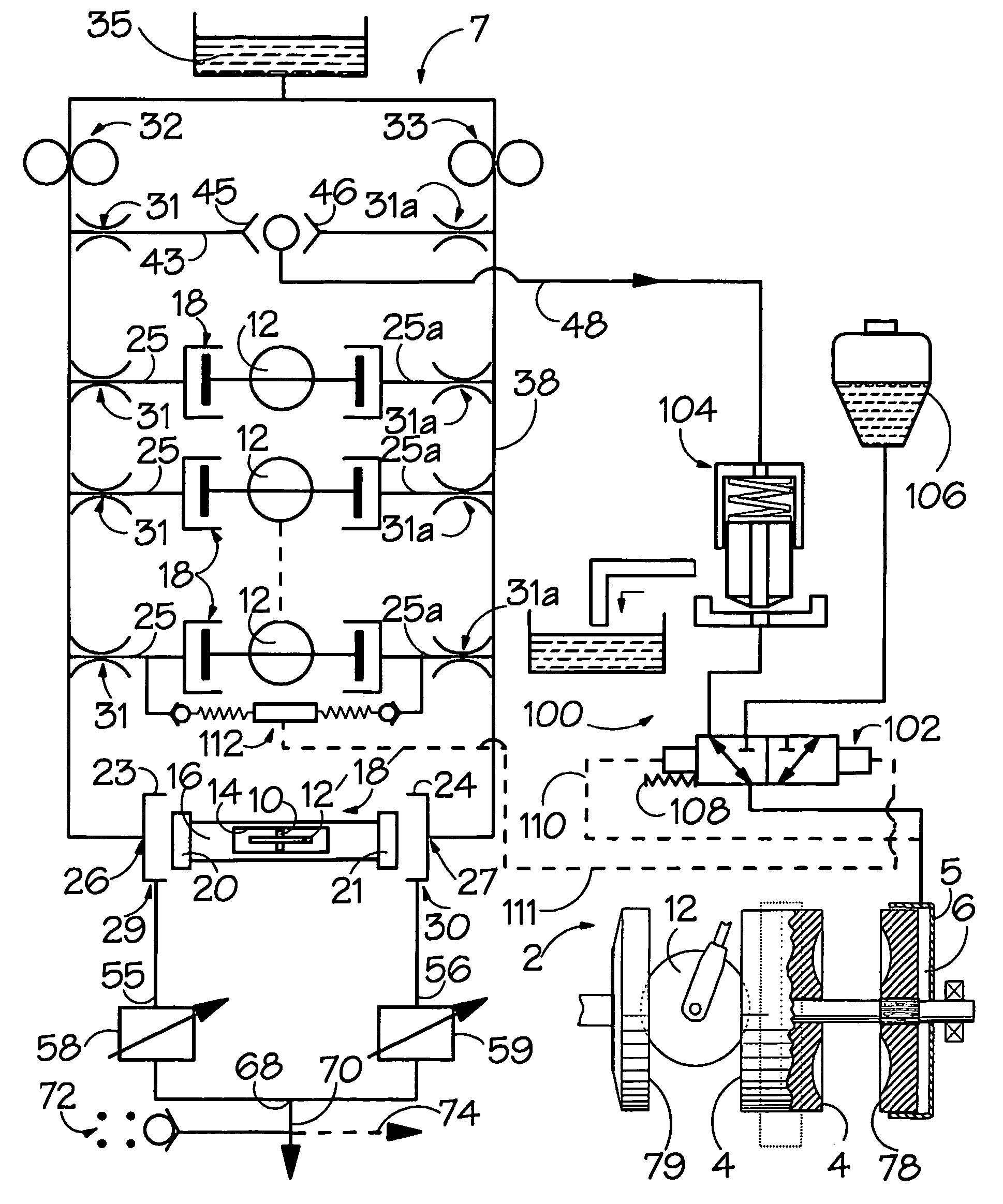
[0046]A variator 2 schematically illustrated in FIG. 1 comprises a pair of input rotor discs 78,79, an output rotor disc 4 and a plurality of rollers 12 situated therebetween for transmission of torque in a manner well known to those skilled in the art and therefore not described in detail herein. At the end of the variator 2 there is provided an end-load assembly 5 which, in its representative form, comprises a simple hydraulic chamber 6 fed with hydraulic fluid at pressure. The pressure in chamber 6 acts to load disc 78 axially such that it clamps the rollers 12 between the discs 4, 78, 79 and enables transmission of torque across the variator. As mentioned above, the magnitude of the end load is to be adjusted in order to achieve an appropriate traction coefficient.

[0047]Turning now to the control circuit 7 of the present embodiment of the invention, it will be appreciated that the axle 10 of a master roller 12′ of the variator is mounted in the cavity 14 of a hollow shaft 16 of ...


PUM


Abstract

A variator assembly comprising a variator of the toroidal-race rolling-traction type. The assembly has input and output discs and rollers which are acted on by hydraulic roller control actuators. They are positioned between the discs to transmit torque from one disc to the other. Hydraulic end loading means supplied with fluid at an end load pressure to apply an end load to bias the discs and the rollers toward each other, thereby enabling the transmission of torque. Reaction pressure supply means are connected to the roller control actuators to cause them to apply an adjustable reaction force to the rollers. The assembly also has hydraulically influenced valve means which serve to compare an input related to the end load pressure with an input related to the reaction pressure and to control the end load pressure in dependence upon the comparison, thereby maintaining a relationship between the end load and reaction pressures. Adjustment means are provided to adjust the relationship between the end load and reaction pressures.

Description

BACKGROUND OF THE INVENTION[0001]1. Field of the Invention[0002]The present invention relates to a hydraulic circuit for controlling a continuously variable ratio unit (“variator”) of the toroidal-race rolling-traction type, and more particularly for controlling an end load in such a variator.[0003]2. Background Art[0004]Toroidal-race rolling-traction type variators are in themselves well known. One, or more typically two, toroidal or part toroidal cavities are defined by opposed faces of rotatably, coaxially mounted discs and drive is transmitted between the discs by rollers disposed in the cavities. It is well known in such variators to mount each roller in a carriage and to connect that carriage to a piston subject to a controlled hydraulic force. So-called “torque control” operation can be achieved in well known manner by applying the hydraulic force along a generally tangential direction (with respect to the axis of the variator discs) and allowing the roller / carriage to move a...

Claims


Application Information

Patent Timeline
Patent Type & Authority Patents(United States)
IPC IPC(8): F16H1/00F16H15/38F16H59/72F16H61/00F16H61/12F16H61/662F16H61/664
CPCF16H61/6649F16H59/72F16H61/12
Inventor GREENWOOD, CHRISTOPHER JOHNFULLER, JOHN WILLIAM EDWARD
Owner ALLISON TRANSMISSION INC
Why Eureka
Try Eureka