Delivering X-ray systems to pipe installations

a technology of x-ray systems and pipe installations, applied in the field of non-contact, non-destructive inspection systems of objects using penetrant radiation, can solve the problems of thinning of pipe walls, moisture trapped in rain and snow, and thinning of external pipe walls, so as to simplify the registration or mapping of objects

Inactive Publication Date: 2008-01-15
GENERAL ELECTRIC CO
View PDF24 Cites 56 Cited by
  • Summary
  • Abstract
  • Description
  • Claims
  • Application Information

AI Technical Summary

Benefits of technology

[0007]A mobile radiographic device for use in inspecting pipelines and the like, comprising an articulating aerial boom coupled to a mobile carriage vehicle. A pivot mount is rotatably coupled to the distal end of the aerial boom. A platform having a sliding rail is operatively coupled to the pivot mount. A mounting fixture, for example, a C-ring fixture, is rotatably mounted to a cradle, which in turn is coupled to the sliding rail of the platform. A radiation source and a radiation detector are positioned by the fixture to direct radiation at and to collect imaging radiation from a pipeline or other object. A first positioning means is provided for coarsely positioning the scanning apparatus relative to the pipeline. A second positioning means is provided for finely positioning the scanning apparatus relative to the pipeline. The second positioning means is operable from a remote location when the radiation source is illuminating the pipeline with radiation. The first and second positioning means provide a plurality of degrees of freedom for positioning the scanning apparatus. The degrees of freedom allow optimal alignment with the objects to be imaged, and simplify registration or mapping of objects, and allow fine movements to perform axial, circumferential, or other scanning of conduits, vessels, and elbows. The mechanism is thus adapted fro imaging with different radiation assemblies, (i.e. X-ray and gamma), imagers (linear array, flat panel), and imaging protocols.

Problems solved by technology

Pipelines, particularly pipelines used in these applications, deteriorate over time, causing a thinning of the pipe walls.
In addition, moisture, such as from rain and snow, can be trapped between insulation placed around the periphery of the pipe and the outer surface of the pipe.
The trapped moisture can corrode the pipe under the insulation, thereby causing a thinning of the external pipe walls.
Thinning of the pipe walls can make the pipeline susceptible to leaking or rupturing, particularly when pressurized.
Failure of the pipe wall, and the resultant leakage, can lead to facility downtime, require expensive repairs, and cause serious injury to workers and the environment.
One disadvantage of such systems is that it is often necessary to dismantle the object under test so that the parts can be moved to a fixed facility for inspection.
In other instances, mobile scanners have been provided for imaging large structures on-site, but such systems tend to be awkward due to their large size and heavy weight, and have generally failed to provide simple, reliable, and responsive drive and control systems for precisely positioning the scanning apparatus over a particular part of the object.
Moreover, such known mobile systems typically require secondary support structures, such as scaffolding, to support personnel access.

Method used


Image

  • Delivering X-ray systems to pipe installations
  • Delivering X-ray systems to pipe installations
  • Delivering X-ray systems to pipe installations

Examples


Embodiment Construction

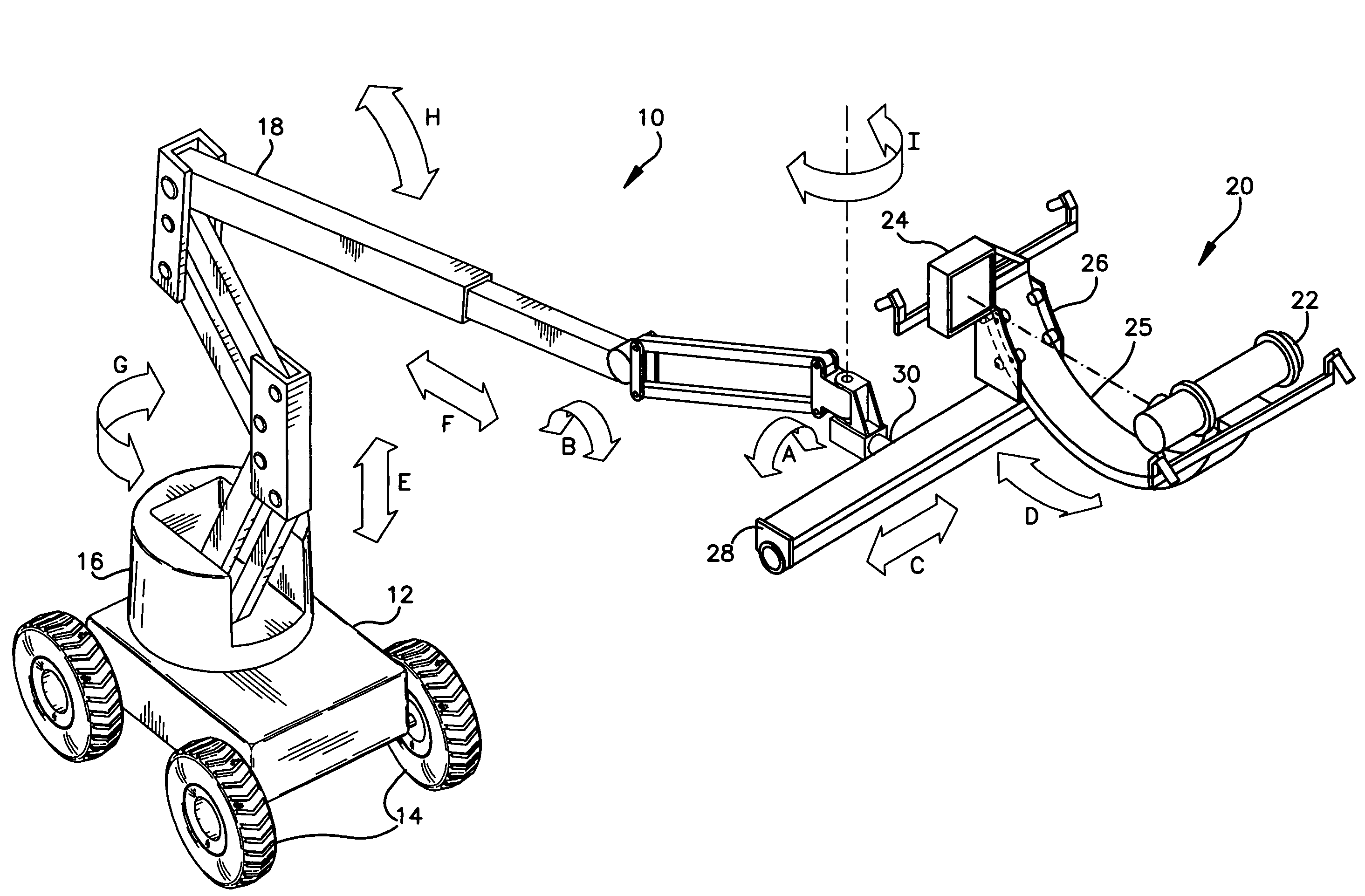
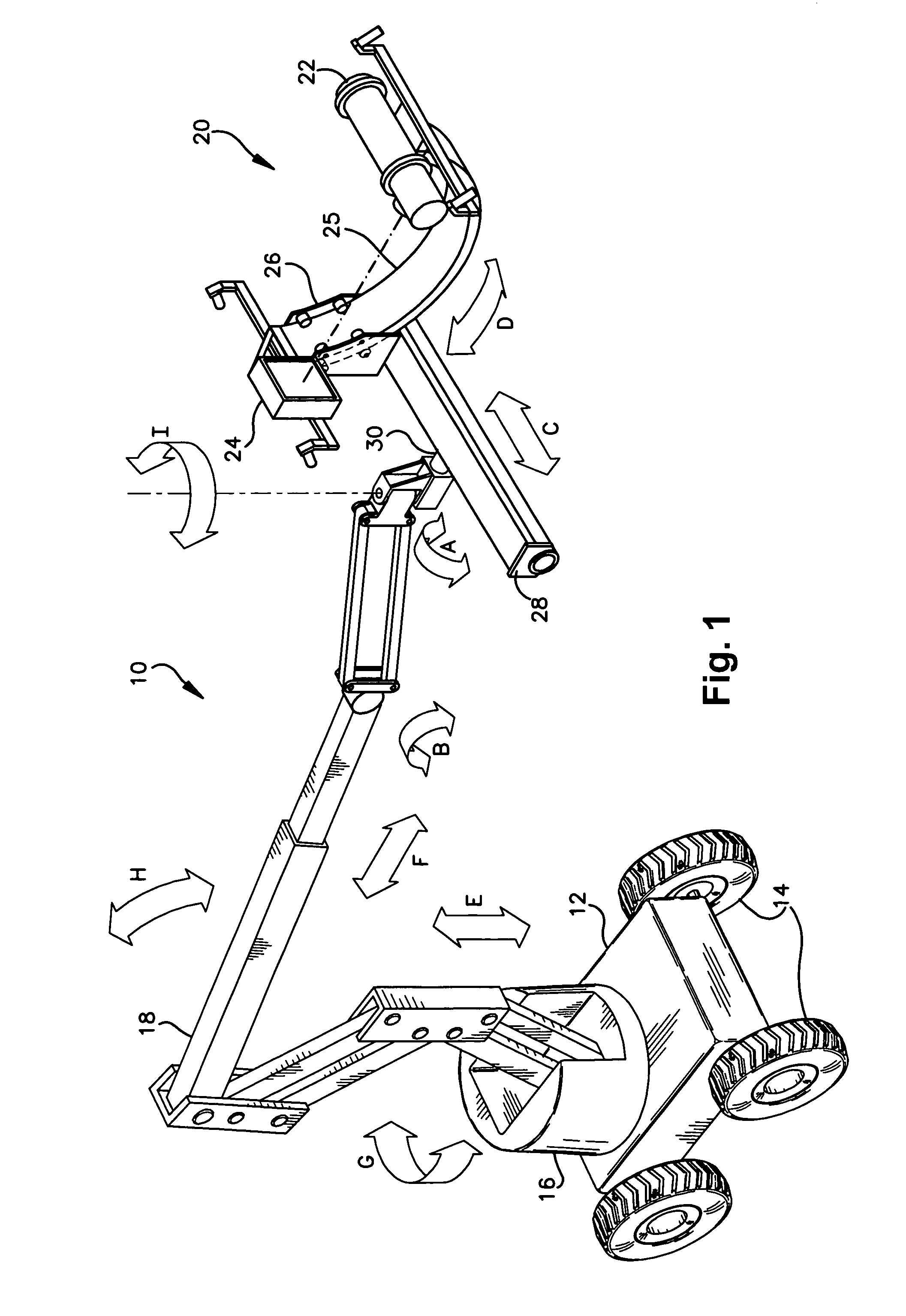
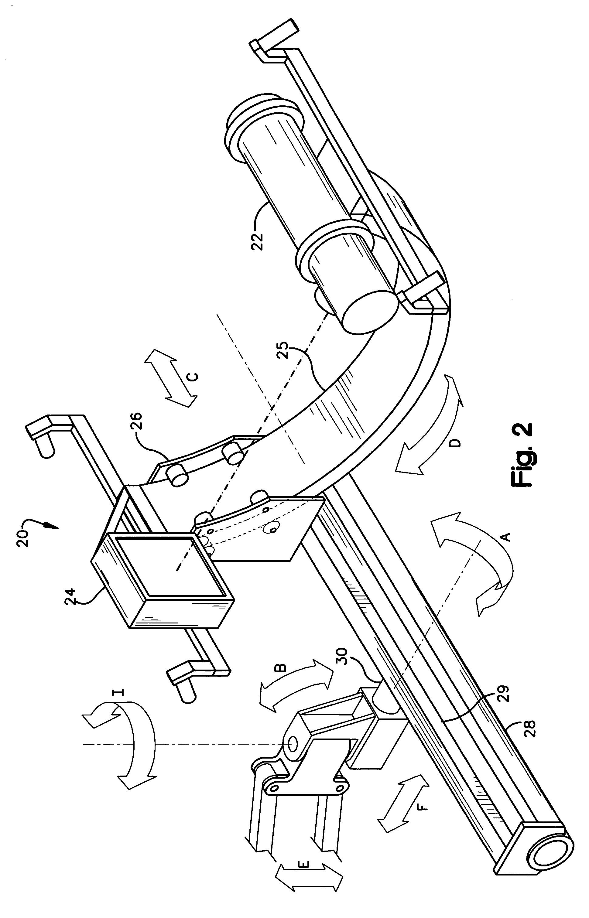
[0015]Exemplary embodiments and examples describing the present invention will be described below with reference to the accompanying drawings. Referring to FIG. 1, a mobile X-ray delivery system is generally indicated by the numeral 10. While the exemplary embodiments described herein pertain to the use of an X-ray source 22 for the generation of X-ray's, it is understood that other types of radiation sources, for example gamma ray sources, could be used without departing from the broader scope of the invention.

[0016]As shown in FIG. 1, the automated X-ray delivery system of the present invention is based on a commercially available man-lift which includes a mobile carriage vehicle 12 supported from the ground by a plurality of wheels 14.

[0017]A turret 16 is mounted to a top surface of the vehicle 12 for supporting the main articulating boom 18. A radiographic scanning system, generally indicated by the number 20, is mounted on the distal end of the main boom 18.

[0018]In the exempla...


PUM

PropertyMeasurementUnit
lengthaaaaaaaaaa
degrees of freedomaaaaaaaaaa
imagingaaaaaaaaaa

Abstract

A mobile radiographic device for use in inspecting pipelines and the like, comprising an articulating aerial boom coupled to a mobile carriage vehicle. A pivot mount is rotatably coupled to the distal end of the aerial boom. A platform having a sliding rail is operatively coupled to the pivot mount. A mounting fixture is rotatably mounted to a cradle, which in turn is coupled to the sliding rail of the platform. A radiation source and a radiation detector are mounted on diametrically opposing sides of the fixture in order to illuminate the outer surface of a pipeline or other object with radiation. A first positioning means is provided for coarsely positioning the scanning apparatus relative to the pipeline. A second positioning means is provided for finely positioning the scanning apparatus relative to the pipeline. The second positioning means is operable from a remote location when the radiation source is illuminating the pipeline with radiation. The first and second positioning means provide a plurality of degrees of freedom for positioning the scanning apparatus.

Description

CROSS-REFERENCE TO RELATED APPLICATION[0001]This application claims the priority benefit of U.S. Provisional Patent Application Ser. No. 60 / 616,986 filed Oct. 8, 2004.FIELD OF INVENTION[0002]The present invention relates generally to a system for non-contact, nondestructive inspection of objects using penetrating radiation and, in particular, relates to a mobile scanning apparatus and method for nondestructive measurements and inspection of stationary components, such as piping, elbows, pumps and diffusers of an operating facility, plant or system while the components are in use for the purpose of determining degradation and condition.BACKGROUND OF THE INVENTION[0003]Pipelines are an integral part of industry, and are widely used in refineries, power plants and other industrial applications. Pipelines, particularly pipelines used in these applications, deteriorate over time, causing a thinning of the pipe walls. Thinning of internal pipe walls can be caused by mechanical stress, flo...

Claims


Application Information

Patent Timeline
Patent Type & Authority Patents(United States)
IPC IPC(8): G01N23/02H05G1/02
CPCG01N23/04
Inventor LASIUK, BRIAN W.GRIFFIN, WESTON B.ALLISON, PETER S.
Owner GENERAL ELECTRIC CO
Why Eureka
Try Eureka