Bill discriminating apparatus

a bill and discrimination technology, applied in the field of bill discrimination apparatus, can solve the problem of not being able to discriminate these types of bills with good precision, and achieve the effect of improving accuracy and good precision

Inactive Publication Date: 2008-01-15
HITACHI OMRON TERMINAL SOLUTIONS CORP
View PDF6 Cites 4 Cited by
  • Summary
  • Abstract
  • Description
  • Claims
  • Application Information

AI Technical Summary

Benefits of technology

[0006]However, among bills to which tape is adhered (hereafter called taped notes), there could be authentic notes which are completely torn bills that are fixed using tape, or bills that look like they will tear that have been reinforced using tape, or counterfeit notes that have been altered by sticking together part of an authentic note and part of a counterfeit note (altered note). In the past, it was not possible to discriminate these types of bills with good precision. Also, with the prior art described above, discrimination of bill authenticity was performed by whether bill thickness was within a specified range, and the precision of authenticity discrimination was improved.
[0007]This technology was created to solve the problems described above, and its purpose is to improve bill discriminating precision.
[0009]The reference thickness distribution data and detected thickness distribution data described above is data that shows the spatial shape of a bill. Therefore, by comparing both of these, it is possible to improve the precision of bill discrimination to be better than prior art authenticity discrimination based on whether the bill thickness is within a specified scope. If the thickness distribution data is made to be three dimensional data that shows the in-plane distribution of a bill, it is possible to further improve the bill discrimination precision. Moreover, detection of bill thickness distribution may also be performed by scanning the bill by having it contact a roller or sensing pin, etc., or by performing this without contact using light or sound waves, etc. Ink irregularities due to intaglio printing are also included in bill thickness distribution.
[0010]Authenticity discrimination is also performed for when the absolute value of the difference between the detected thickness distribution data and the reference thickness distribution data is in a range of a specified threshold value or less. This is because for areas for which the absolute value of the difference between the detected thickness distribution data and the reference thickness distribution data is greater than a specified threshold value, this can be regarded as the thickness of the bill itself being thick, as multiple bills overlapping, as the thickness of the bill itself being thin, or as an adhered item such as tape being adhered to part of the bill or as being missing. By working in this way, even if there is adherence of tape, etc. or if there are abnormalities in the dimensions or thickness, it is possible to perform discrimination by effectively using other normal range data. For example, for a bill that is an authentic note which has been reinforced using tape, it is possible to determine this to be an “authentic note.”

Problems solved by technology

In the past, it was not possible to discriminate these types of bills with good precision.

Method used


Image

  • Bill discriminating apparatus
  • Bill discriminating apparatus
  • Bill discriminating apparatus

Examples


example 1

F1. Variation Example 1

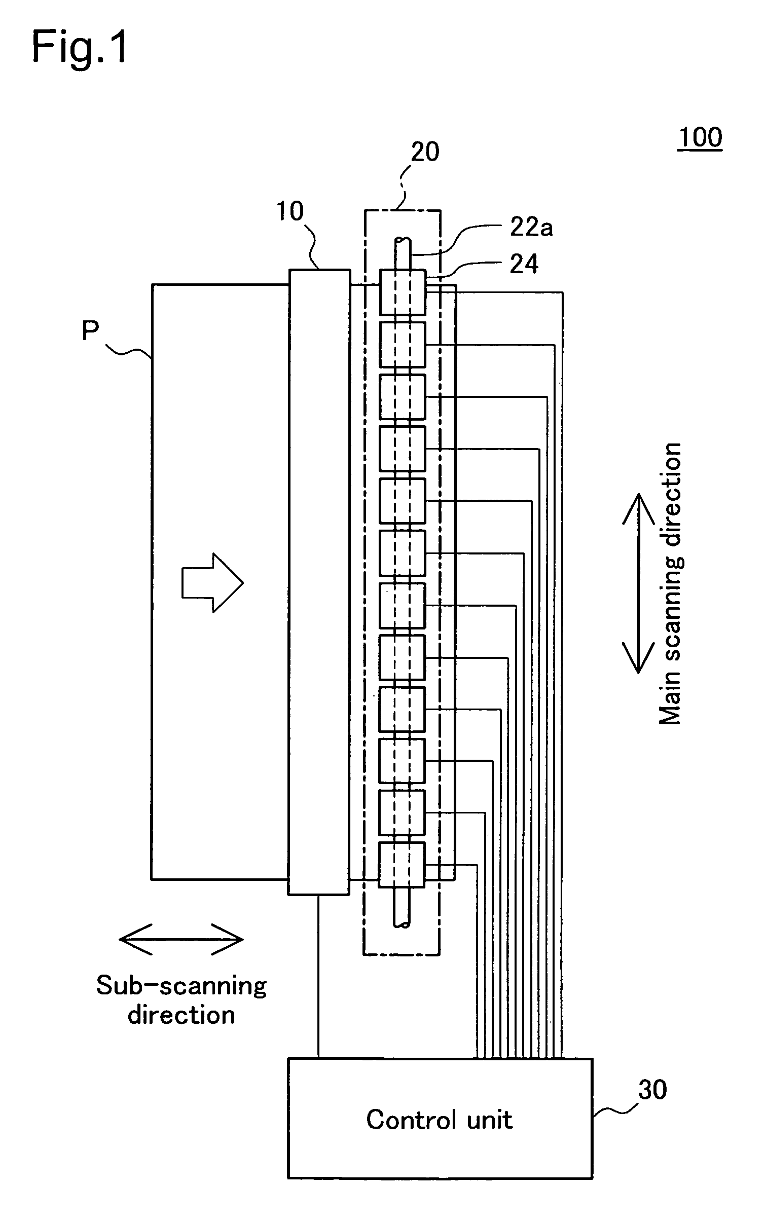
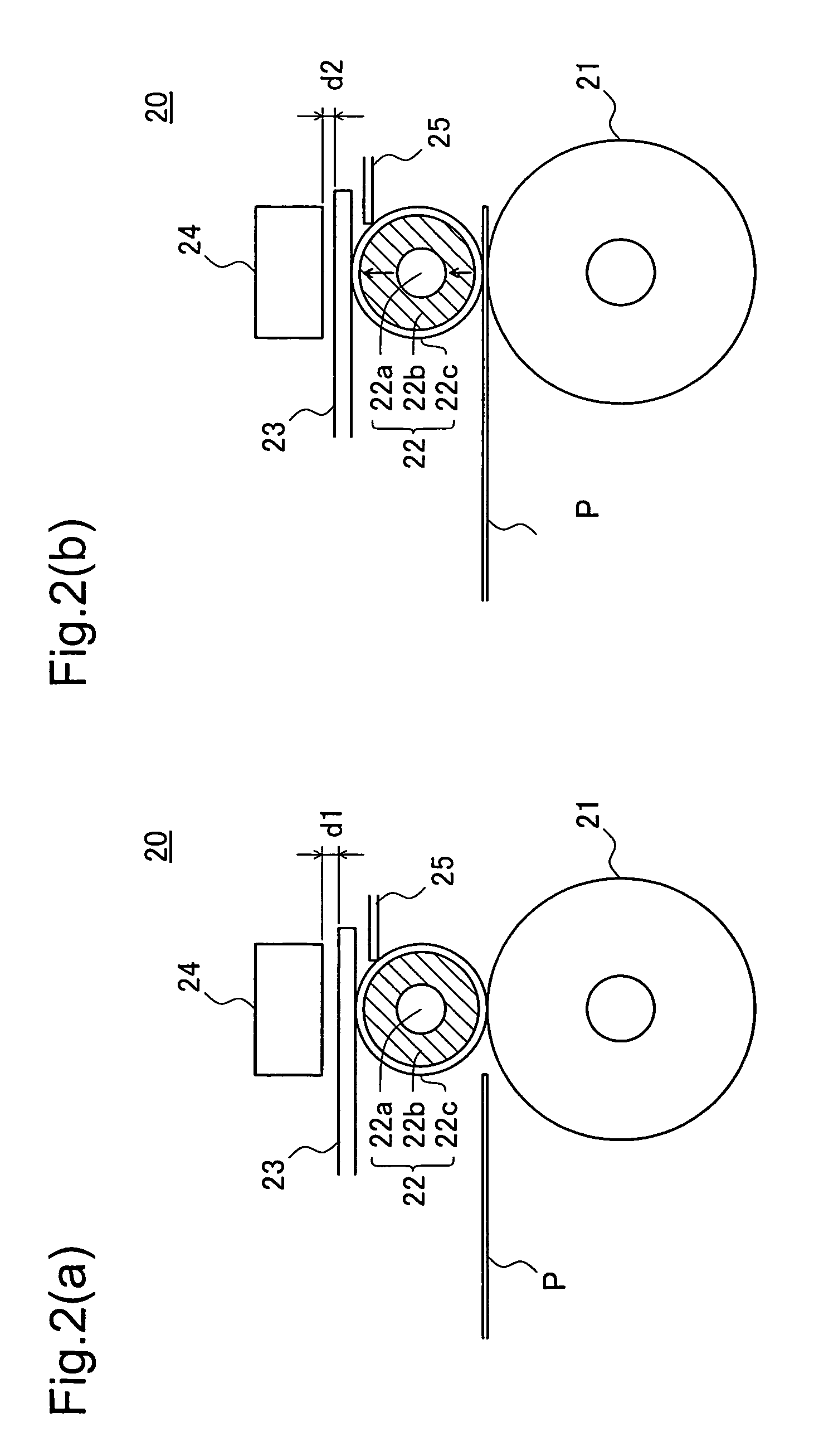
[0080]FIG. 12 shows the schematic structure of a thickness detection mechanism 20A as a variation example. The same as the thickness detection mechanism 20 shown in FIG. 2, the thickness detection mechanism 20A shows the state seen from the side (main scanning direction).

[0081]The thickness detection mechanism 20A comprises a detection roller 22d and an arm 23a of this detection roller 22d in place of the detection roller 22 and plate spring 23 that form the thickness detection mechanism 20. Then, the detection roller 22d is supported on the arm 23a by the axis 3c, and the arm 23a is supported on the thickness detection mechanism 20A by the axis 23b. The axis 23b is common to twelve arms 23a. The structure other than this is the same as for the thickness detection mechanism 20.

[0082]By detecting changes in the electrostatic capacity of the gap between the sensor 24 and the arm 23a, the sensor 24 is able to detect changes in the distance d between the sensor 24...

example 3

F3. Variation Example 3

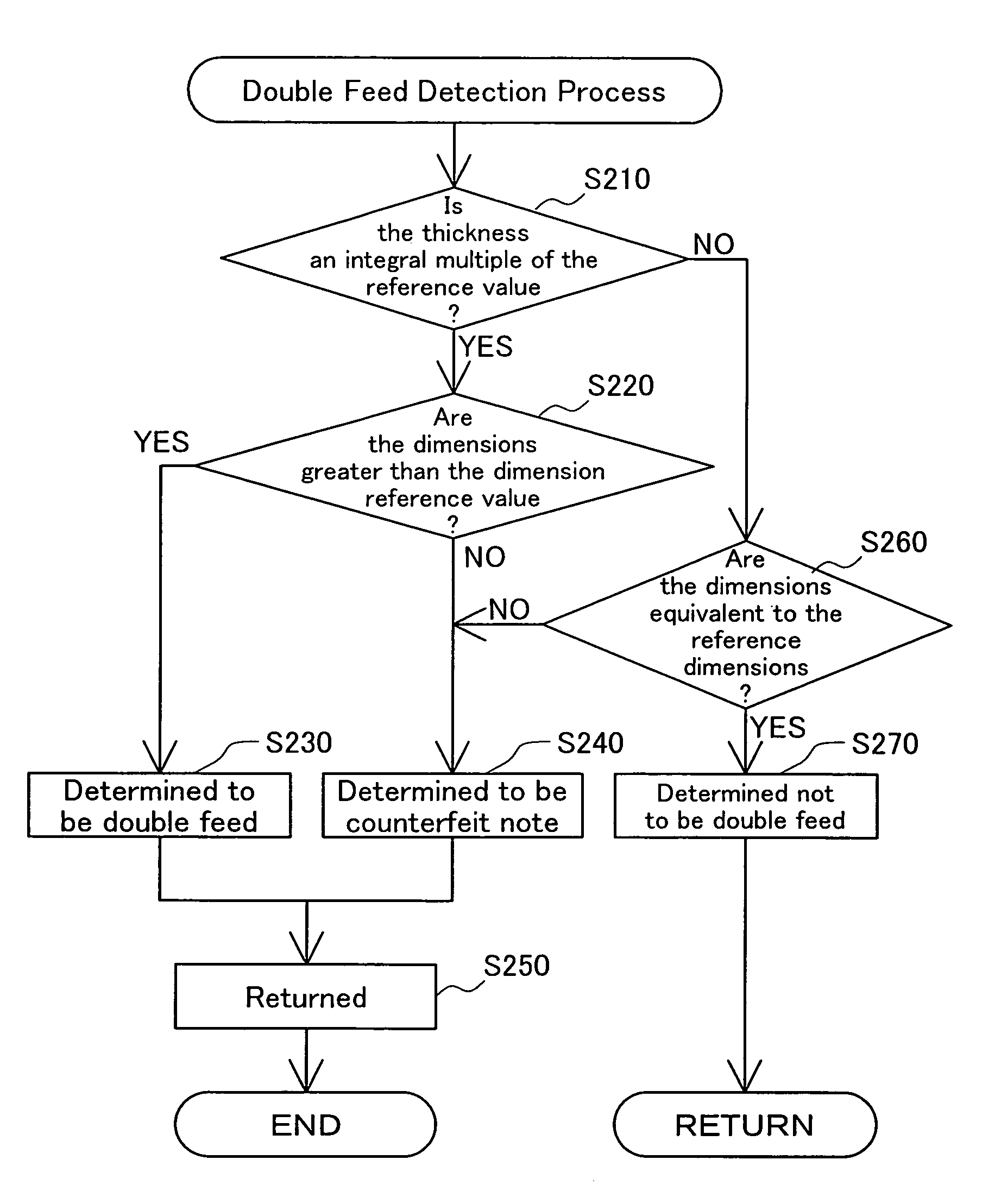
[0085]With the aforementioned embodiment, the threshold value tht shown in FIG. 7 is set so that it may be set freely according to the thickness of the tape T. It is also possible to have the discrimination unit 33 equipped with a threshold value setting unit for automatically setting the threshold value tht. This threshold setting unit could, for example, be made so as to set the threshold value tht based on statistical analysis of, for example, detected thickness distribution data, or of the difference between the detected thickness distribution data and the reference thickness distribution data (e.g. maximum value, minimum value, average value, variance, deviation, etc.). By working in this way, it is possible to further improve the discrimination precision.

F4. Variation Example 4

[0086]With the aforementioned embodiments, the corrected distribution data generating unit 333 was made to correct thickness distribution data based on the conveyance position, but...


PUM


Abstract

A technology that increases bill discrimination precision, wherein a bill discriminating apparatus detects the thickness distribution of a bill P that is subject to discrimination, and by comparing this thickness distribution data and the reference thickness distribution data that shows the thickness distribution of an authentic note held in advance, performs discrimination processing that includes double feed detection, tape detection, and authenticity discrimination. Then, authenticity discrimination is performed on areas for which the difference between the thickness distribution data and the reference thickness data is within a specified range.

Description

BACKGROUND OF THE INVENTION[0001]This technology relates to a bill discriminating apparatus that performs bill discrimination.[0002]Prior Art[0003]Bill discriminating apparatuses for performing bill discrimination are incorporated in cash automatic teller machines (ATM) installed at financial institutions, etc. and in automatic vending machines. A variety of discrimination technologies were proposed for this bill discriminating apparatus in the past. As one of these discrimination technologies, there is a technology that discriminates bills to which a foreign object such as tape is adhered.[0004]For example, with the bill discriminating apparatus noted in Japanese Patent Laid-Open Gazette No. 7-6245, by comparing the detection voltage in relation to the thickness of a bill type, the tape detection reference voltage, and the negotiable security detection reference voltage, a detection is made of whether or not there is tape. Then, furthermore, when tape is adhered extending to both e...

Claims


Application Information

Patent Timeline
Patent Type & Authority Patents(United States)
IPC IPC(8): G06K9/00G06T1/00G01B21/08G07D7/00G07D7/16G07D7/182G07D7/20
CPCG07D7/164G07D7/166G07D7/187G07D7/183
Inventor MORI, AKIRANAKABAYASHI, MUNEHARU
Owner HITACHI OMRON TERMINAL SOLUTIONS CORP
Why Eureka
Try Eureka