Method and device for controlling a movement of a movable machine element of a machine tool or production machine

a technology of a machine tool or a production machine, applied in the direction of program control, electric programme control, instruments, etc., can solve the problems of limited number of options for preventing excitation, adversely affecting the actual position value of a machine element, and not noticeable improvement over a conventional operation without input shaping

Inactive Publication Date: 2008-01-15
SIEMENS AG
View PDF18 Cites 9 Cited by
  • Summary
  • Abstract
  • Description
  • Claims
  • Application Information

AI Technical Summary

Benefits of technology

[0036]Tv=abs⁢12*(12⁢fdv-12⁢fd),wherein fdv is the mechanical characteristic frequency of a drive axle v with a mechanical characteristic frequency higher than the lowest mechanical characteristic frequency and fd is the mechanical characteristic frequency of the drive axle with the lowest mechanical characteristic frequency. This approach can significantly reduce distortions in the contour resulting from “Input Shaping”.
[0038]According to yet another advantageous feature of the invention, the delay unit can be an integral component of the controller or of a closed-loop controller. The delay units can easily be integrated in an already existing controller and / or in existing closed-loop controllers or in the control units without requiring additional hardware, in particular when the machine tool or production machine already includes a numerical controller.

Problems solved by technology

A mechanical system capable of oscillations (for example, a drive axle of a machine tool or production machine) is typically characterized by at least one characteristic frequency that can be excited during a movement and can adversely affect the actual position value of, for example, a machine element.
Because the jerk and the acceleration values are controlled along the movement path S of the machine element, there exist only a limited number of options for preventing excitation of oscillations, in particular excitation at the respective characteristic frequency of geometrically linked drive axles.
When the afore-described method of “Input Shaping” is applied to machine tools or production machines with geometrically linked drive axles that have different mechanical characteristic frequencies, which is practically always the case, then the problem illustrated in FIG. 7 arises.
Although mechanical oscillations are no longer excited with “Input Shaping,” the result is not noticeably improved over a conventional operation without “Input Shaping.”

Method used


Image

  • Method and device for controlling a movement of a movable machine element of a machine tool or production machine
  • Method and device for controlling a movement of a movable machine element of a machine tool or production machine
  • Method and device for controlling a movement of a movable machine element of a machine tool or production machine

Examples


Embodiment Construction

[0055]Throughout all the Figures, same or corresponding elements are generally indicated by same reference numerals. These depicted embodiments are to be understood as illustrative of the invention and not as limiting in any way. It should also be understood that the drawings are not necessarily to scale and that the embodiments are sometimes illustrated by graphic symbols, phantom lines, diagrammatic representations and fragmentary views. In certain instances, details which are not necessary for an understanding of the present invention or which render other details difficult to perceive may have been omitted.

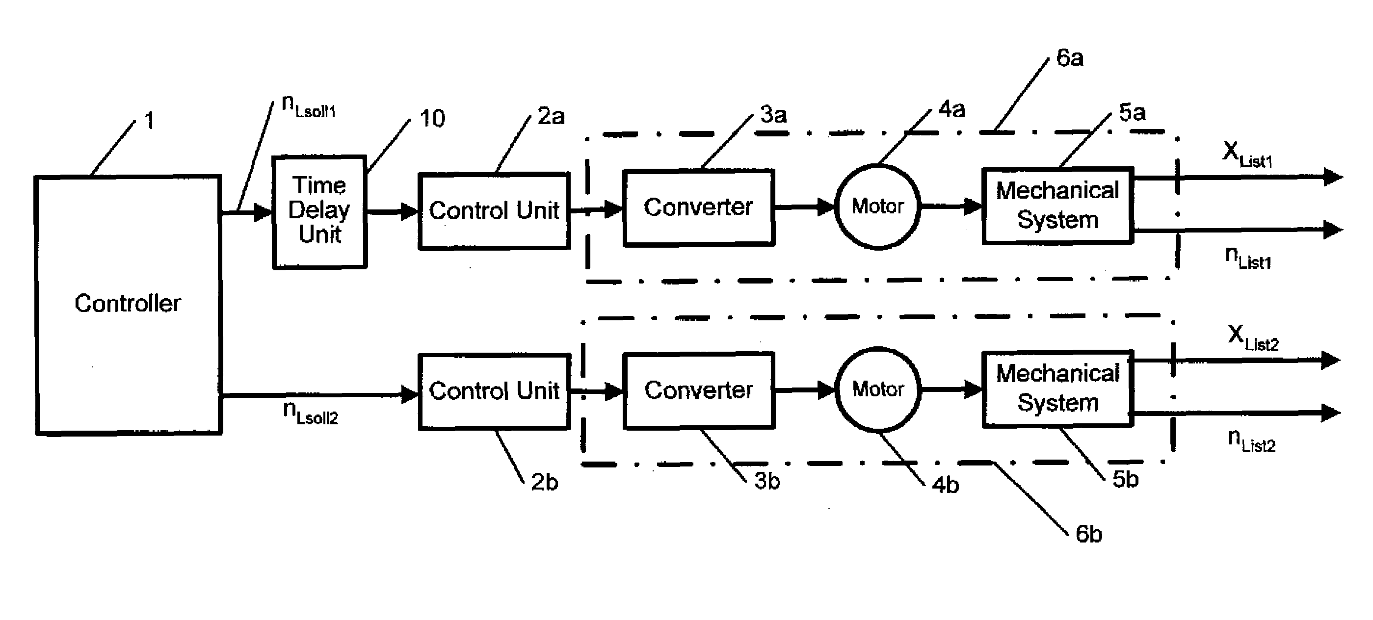
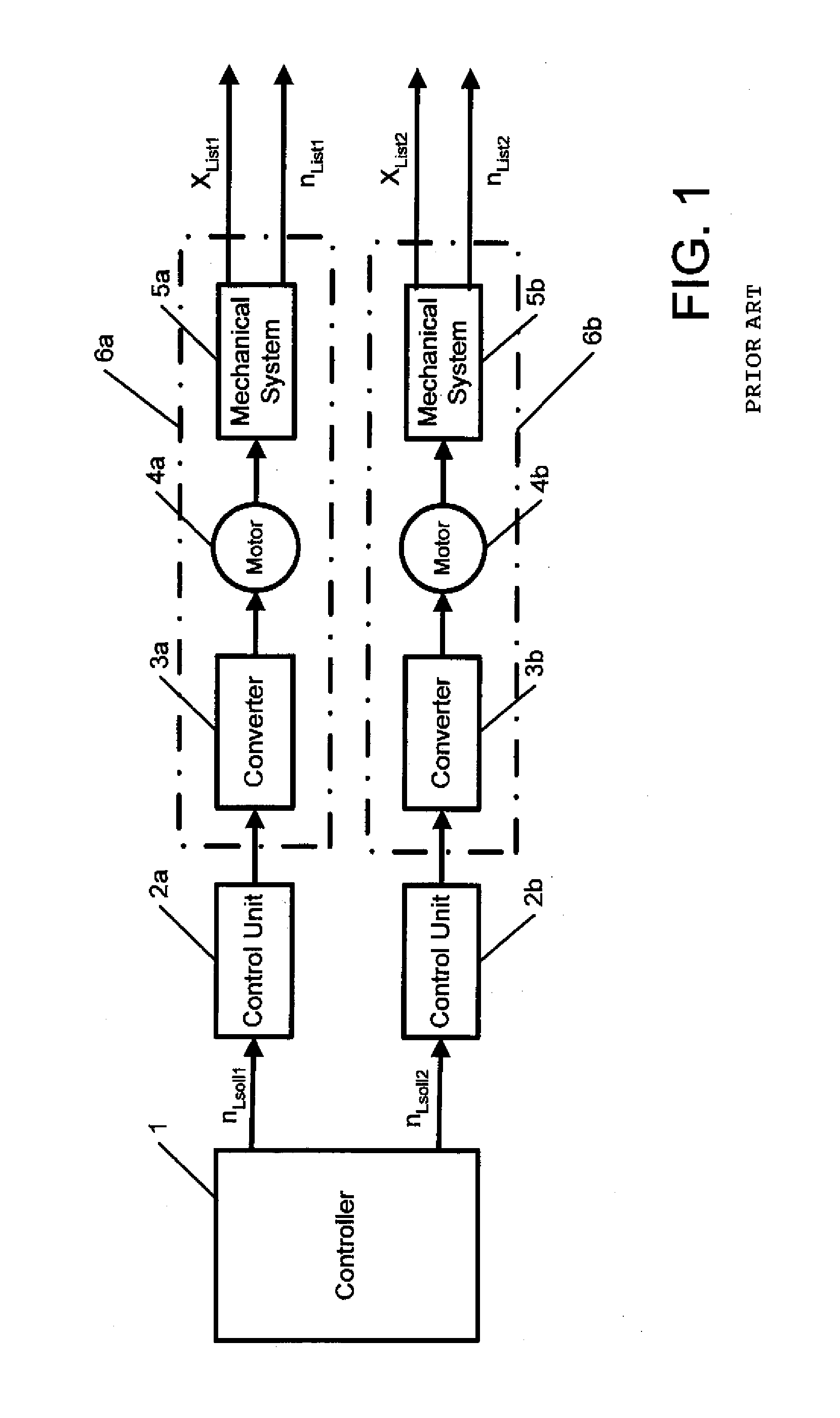
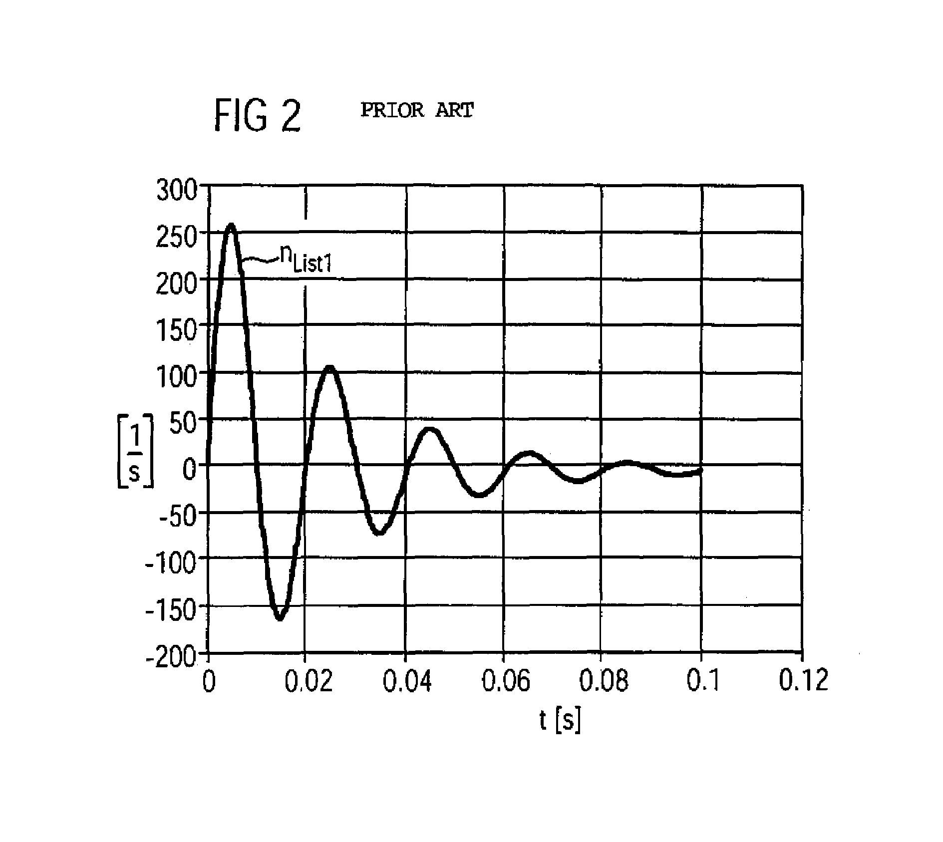
[0056]As mentioned above, the method of “Input Shaping” has not been applied to machines with drive axles that are geometrically linked and have different characteristic oscillation frequencies, because the results are unsatisfactory, as indicated in FIG. 7. The inventor has investigated the underlying causes for these unsatisfactory results, which were not known to date.

[0057...


PUM


Abstract

A method and device for controlling a movement of a movable machine element of a machine tool or production machine with at least two drive axles are disclosed. At least one mechanical characteristic frequency is determined for each drive axle of the machine, and the lowest mechanical characteristic frequency is selected from the determined mechanical characteristic frequencies. For each drive axle of the machine, desired values are supplied to a control unit associated with the drive axle, whereby the desired values of the drive axles having a mechanical characteristic frequency higher than the lowest mechanical characteristic frequency are time-delayed. The disclosed method and device modify a method referred to as “Input Shaping” so that geometrically linked drive axles can be operated simultaneously.

Description

CROSS-REFERENCES TO RELATED APPLICATIONS[0001]This application claims the priority of German Patent Application, Serial No. 103 59 984.3, filed Dec. 19, 2003, pursuant to 35 U.S.C. 119(a)-(d).BACKGROUND OF THE INVENTION[0002]The present invention relates to a method and a device for controlling a movement of a movable machine element of a machine tool or production machine with at least two drive axles.[0003]Nothing in the following discussion of the state of the art is to be construed as an admission of prior art.[0004]A mechanical system capable of oscillations (for example, a drive axle of a machine tool or production machine) is typically characterized by at least one characteristic frequency that can be excited during a movement and can adversely affect the actual position value of, for example, a machine element. Excitations the mechanical system of the machine should therefore be prevented.[0005]FIG. 1 shows in form of a block diagram a prior art electric drive system of a ma...

Claims


Application Information

Patent Timeline
Patent Type & Authority Patents(United States)
IPC IPC(8): F16F15/20G05B19/19
CPCG05B19/19G05B2219/41414G05B2219/50216
Inventor PAPIERNIK, WOLFGANG
Owner SIEMENS AG
Why Eureka
Try Eureka