Anti-terrorism vehicle security barrier

Active Publication Date: 2008-01-22
PRO BARRIER ENG
View PDF9 Cites 34 Cited by
  • Summary
  • Abstract
  • Description
  • Claims
  • Application Information

AI Technical Summary

Benefits of technology

[0013]It is an object of this invention to provide a vehicle bar

Problems solved by technology

Since the portable plate barrier is not imbedded in concrete, stopping power is relatively limited.
Generally, bollards are a permanent structure that cannot be made portable without loss of substantial stopping power capabilities.
Conventional barriers have another disadvantage inherent in their designs in that each barrier design requires active mechanical movement of very heavy structures.
Many facilities simply do not have the necessary space to accommodate this type of operation.
This means that many existing barriers are seldom used in an “activate only when needed” mode.
In a

Method used


Image

  • Anti-terrorism vehicle security barrier
  • Anti-terrorism vehicle security barrier
  • Anti-terrorism vehicle security barrier

Examples


Embodiment Construction

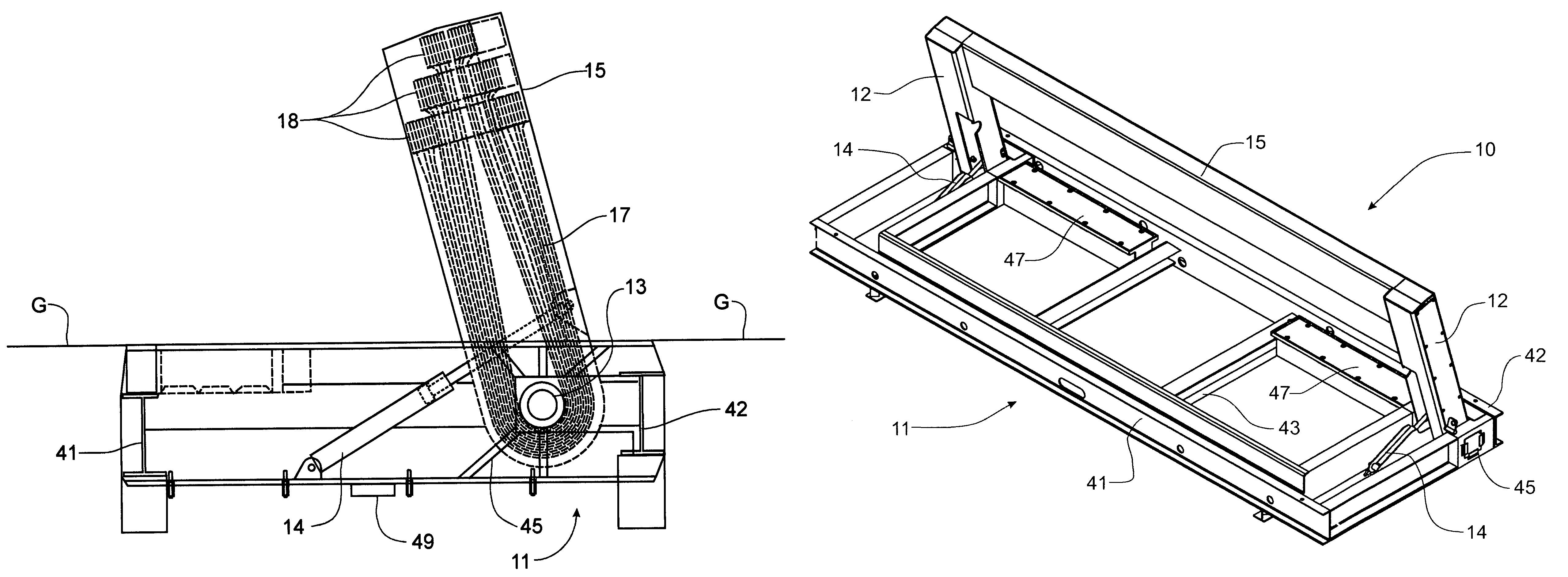
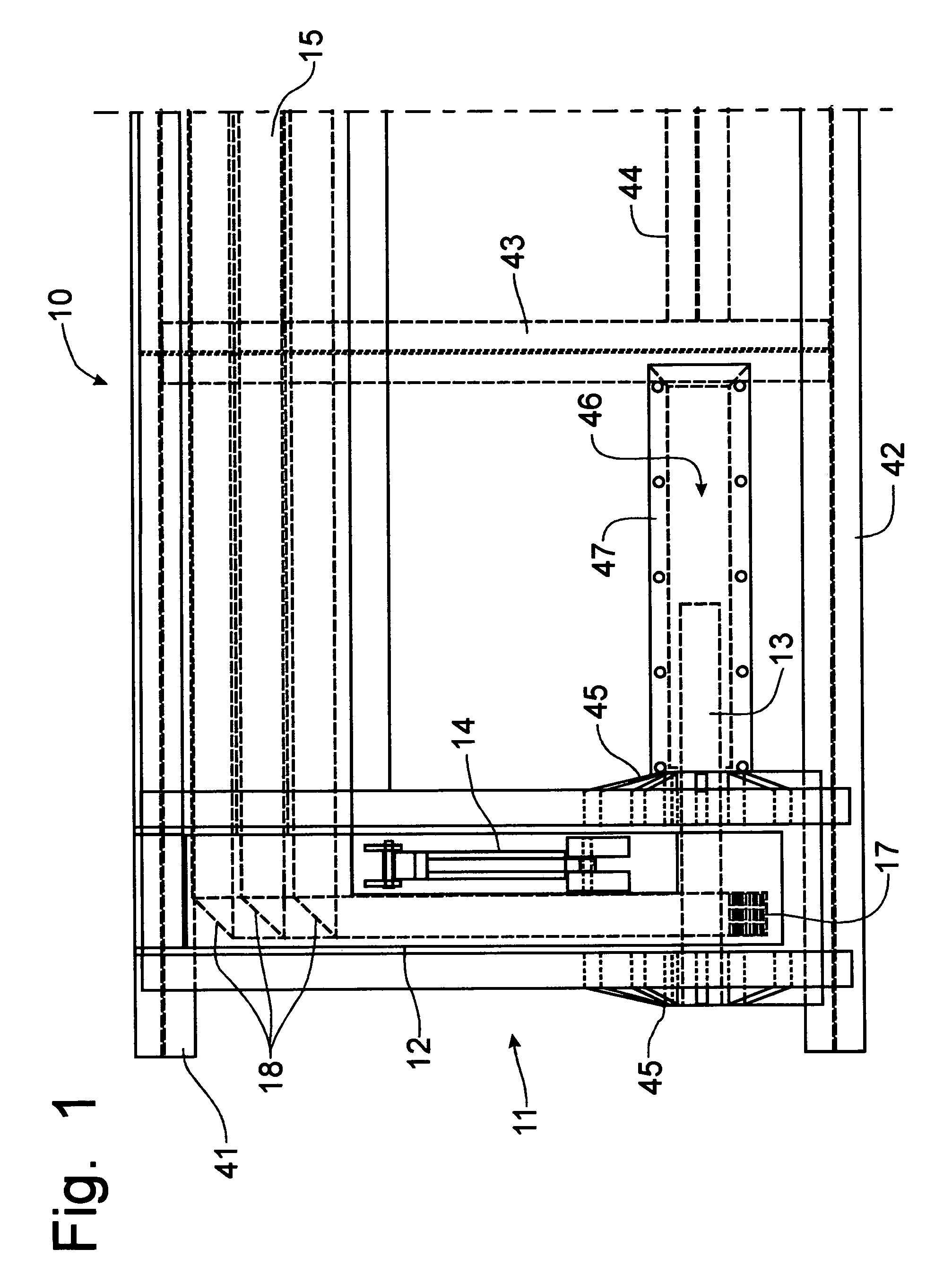
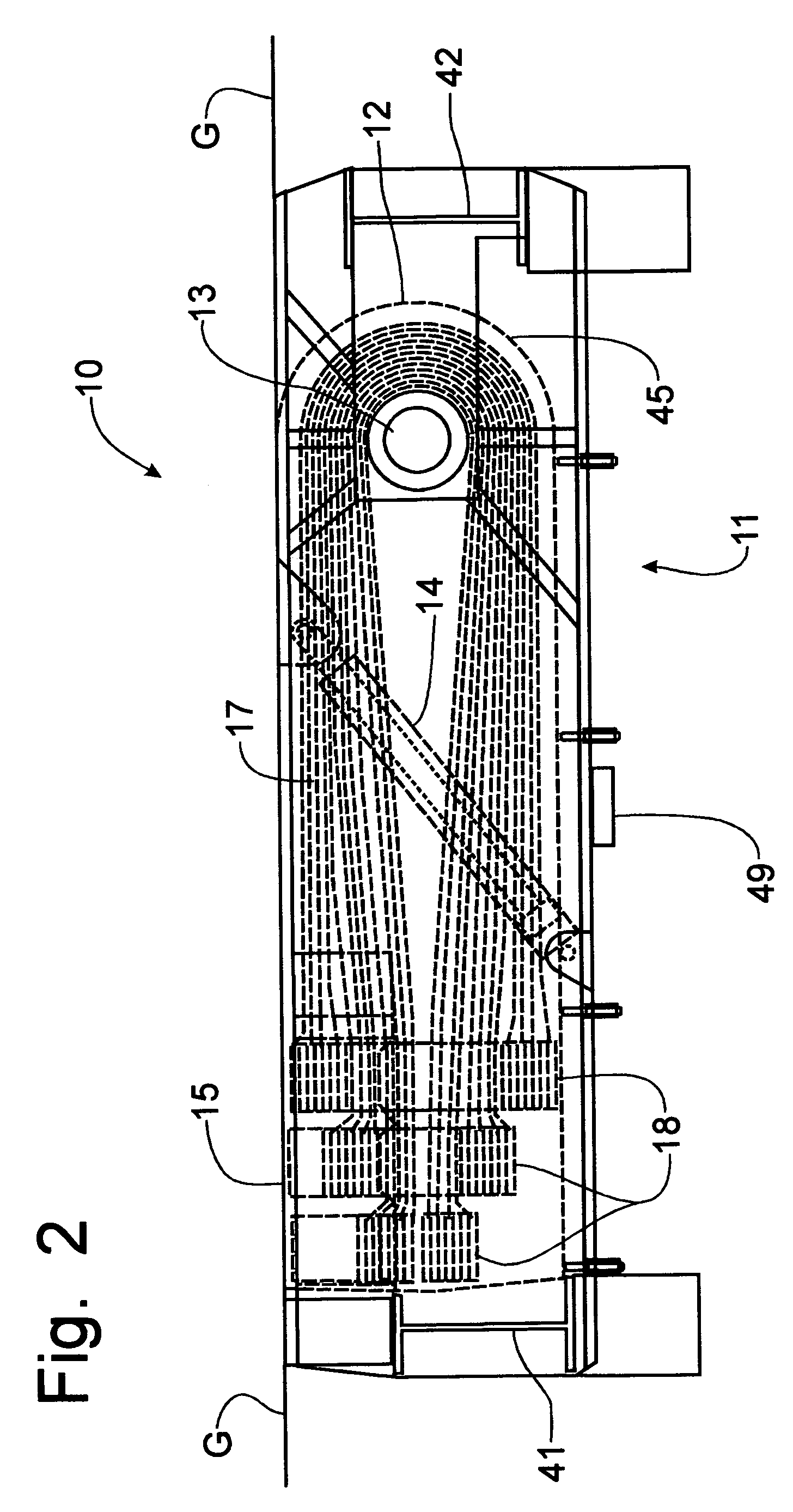
[0059]Referring now to FIGS. 1-5 and 19-21, a vehicle security barrier incorporating the principles of the instant invention can best be seen. The configuration of the barrier 10 depicted in FIGS. 1-5 is a permanent installation, as opposed to the portable version depicted in FIGS. 6-12 and described in greater detail below. The installation of a permanent vehicle security barrier 10 requires an excavation of the road surface to install the components below the finished grade of the road surface G so that the back side of the barrier beam 15 is oriented substantially flush with the road surface G, as is depicted in FIG. 19 so as to not interfere with the passage of a vehicle when the barrier is in a lowered or open orientation.

[0060]The barrier 10 is formed with transversely opposing pivot arms 12 that are pivotally mounted for vertical movement about a horizontal, transversely disposed pivot shaft 13. Movement of the pivot arms 12 is accomplished by hydraulic cylinders 14 anchored ...


PUM


Abstract

A vehicle barrier is formed with a barrier gate mounted on a pair of opposing lift arms pivotally connected via pivot shafts to a support structure. A plurality of endless bands are looped around the opposing pivot shafts and positioned to pass through compartments in the barrier gate. The lift arms and the barrier gate may be fabricated from lightweight material, such as thin steel, aluminum or plastic, so that the stopping power of the vehicle barrier is provided by the anchored bands. In permanent or portable configurations, the lightweight barrier gate can be quickly raised by hydraulic cylinders, or other appropriate means, into a deployed position to interfere with the passage of a vehicle over the barrier. The anchoring of the bands at ground or below ground locations on both sides of the barrier provides stopping power without requiring massive barrier structures to be raised and lowered in use.

Description

CROSS-REFERENCE TO RELATED APPLICATIONS[0001]This application claims domestic priority on U.S. Provisional Patent Application Ser. No. 60 / 616,169, filed on Oct. 5, 2004, the contents of which are incorporated herein by reference.BACKGROUND OF THE INVENTION[0002]The present invention relates generally to devices for preventing vehicles from passing beyond a predetermined point in a roadway to provide security control and, more particularly, to a roadway barrier that can be selectively actuated to restrict access over a roadway[0003]The present invention also relates to an apparatus for transporting multiple portable crash barriers and, more particularly, to a transporter mechanism for positioning portable crash barriers after delivery thereof to a deployment location.[0004]For many years, a small number of companies have sold vehicle crash barriers primarily designed to thwart deliberate vehicle-based attacks of buildings. These barriers are generally heavy steel structures imbedded ...

Claims


Application Information

Patent Timeline
IPC IPC(8): E01F13/00
CPCE01F13/123
Inventor POTTER, THOMAS E.
Owner PRO BARRIER ENG
Why Eureka
Try Eureka