Electric distribution box and method of assembling the same

a technology of electric distribution box and assembling method, which is applied in the directions of coupling device details, coupling device connection, transportation and packaging, etc., can solve the problems of increasing the size of the electric distribution box, the cost of assembling operation, and the time and labor required for assembling operation, so as to achieve the effect of time and labor

Inactive Publication Date: 2008-01-22
YAZAKI CORP
View PDF14 Cites 20 Cited by
  • Summary
  • Abstract
  • Description
  • Claims
  • Application Information

AI Technical Summary

Benefits of technology

[0008]This invention has been made in view of the above circumstances, and an object of the invention is to provide an electric distribution box in which a compact design thereof can be achieved, and besides the time and labor, required for an assembling operation, can be reduced and a method of assembling the electric distribution box.
[0010]In the invention of the above Paragraph 1), the fuse holder and the connector block are mounted on an outer peripheral edge portion of the printed circuit board, and the power bus bar is fixed to that portion of the printed circuit board lying between the fuse holder and the connector block, so that the fuse holder, the connector block and the power bus bar are disposed generally on a common plane. Therefore, the height of the electric distribution box can be reduced, thereby achieving a compact design thereof, and besides the time and labor, required for the assembling operation, can be reduced.
[0012]In the invention of the above Paragraph 2), the plurality of relays are fitted in the power bus bar, and therefore heat, generated by an arc developing between contacts upon operation of each relay, is less liable to be transmitted to the printed circuit board. As a result, a failure due to heat can be avoided, so that the quality can be enhanced.
[0014]In the invention of the above Paragraph 3), the relays are fixed to that portion of the printed circuit board lying between the fuse holder and the connector block, and with this arrangement the relays can be disposed generally on the plane in which the fuse holder and the connector block are disposed. And besides, a bent portion, forming a circuit for a controller mounted near to the power bus bar, can be easily formed. As a result, the overall structure, including the relays, can be made compact, and besides the circuit for the controller can be formed at the shortest distance.
[0016]In the invention of the above Paragraph 4), the power bus bar is formed into an integral construction by insert molding, and thereafter interconnecting portions are cut off, thereby providing the separate distribution bus bars required for forming the circuits. Therefore, the general-purpose ability can be enhanced.
[0017]The electric distribution box of the present invention can solve the problems that its size increases, that it is difficult to connect the circuits at a high density and that the time and labor required for the assembling operation, as well as the cost of the assembling operation, can not be reduced since the joining technique such as soldering is required. Therefore, there are achieved advantages that the compact size can be achieved and that the time and labor for the assembling operation can be reduced.

Problems solved by technology

Therefore, there has been encountered a problem that a dead space is liable to be formed within the receiving space formed by the covers, so that the size of the electric distribution box increases, and also there has been encountered another problem that it is difficult to connect circuits at a high density.
Cumbersome joining technique (such as soldering) is required for electrically connecting the circuit boards 105 and 106, the connectors 107 and 108, the fuse mounting portion 109, the relay mounting portion 110 and so on to one anther so as to form circuits, and this has invited a problem that the time and labor required for the assembling operation, as well as the cost of the assembling operation, can not be reduced.

Method used


Image

  • Electric distribution box and method of assembling the same
  • Electric distribution box and method of assembling the same
  • Electric distribution box and method of assembling the same

Examples


Embodiment Construction

[0051]A preferred embodiment of the present invention will now be described in detail with reference to the drawings.

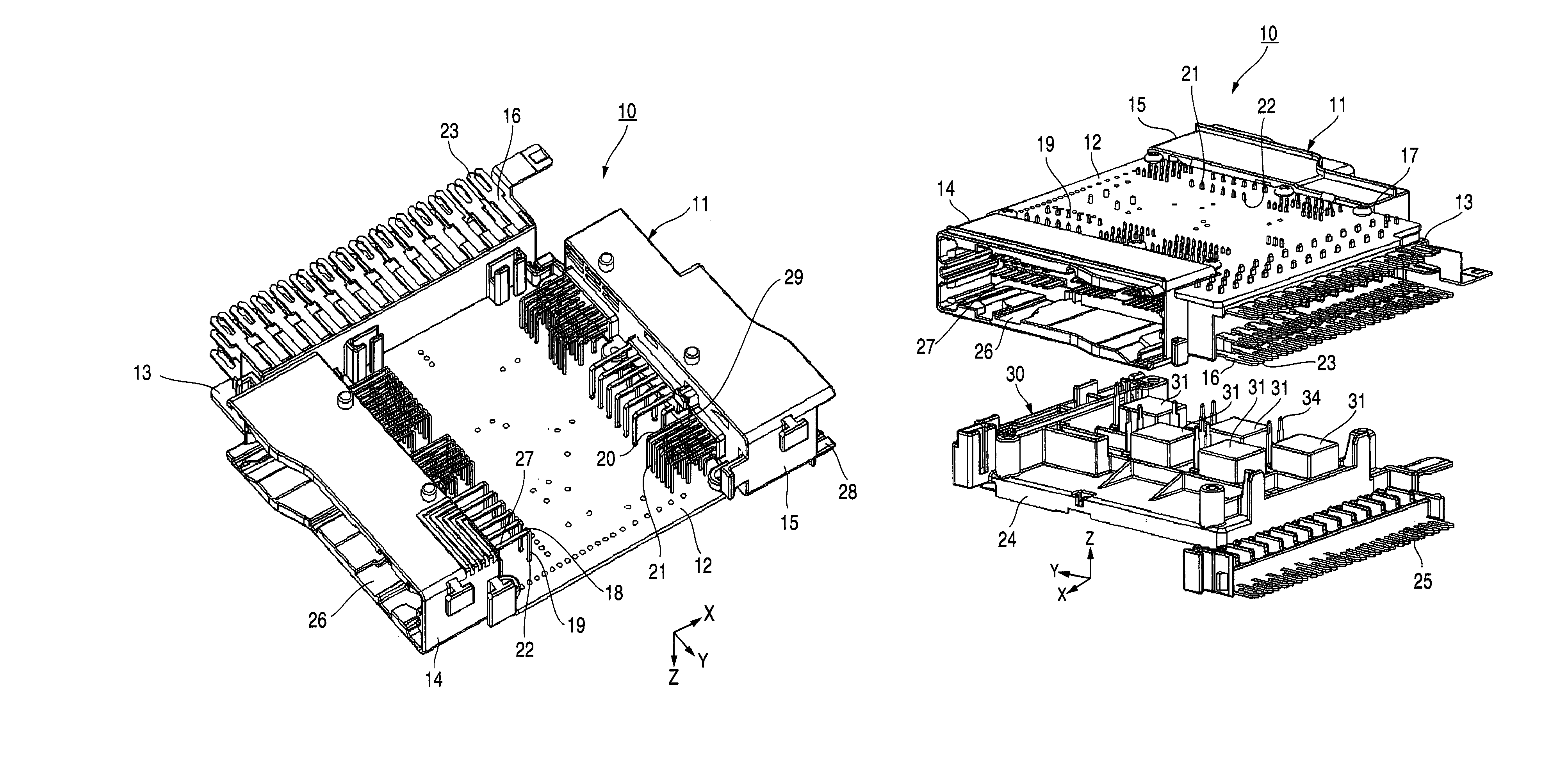
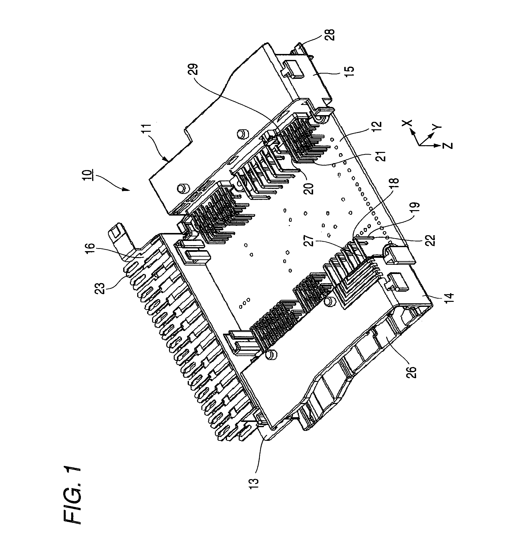
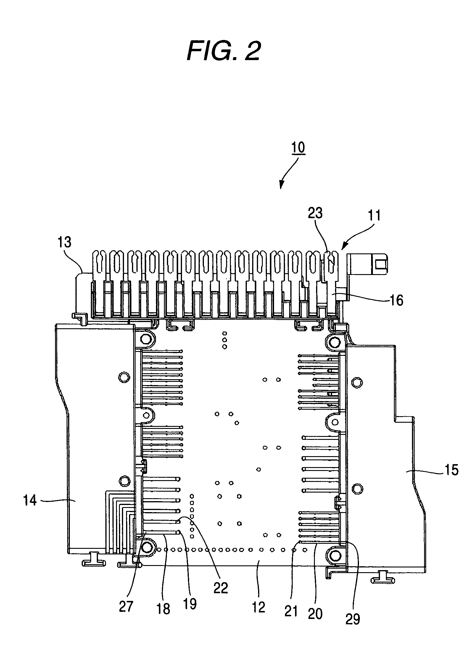
[0052]FIG. 1 is a perspective view of a first assembly used in one preferred embodiment of an electric distribution box of the present invention, FIG. 2 is a plan view of the first assembly of FIG. 1, FIG. 3 is a perspective view of a second assembly of the electric distribution box of the invention, FIG. 4 is a plan view of the second assembly of FIG. 3, FIG. 5 is a perspective view explaining the manner of assembling the first and second assemblies together, FIG. 6 is a perspective view of the electric distribution box as seen from the lower side of FIG. 5, FIG. 7 is a perspective view of the electric distribution box of FIG. 6 in its assembled condition, and FIG. 8 is a cross-sectional view of the electric distribution box of FIG. 7.

[0053]As shown in FIG. 1, the first assembly 11 of the preferred embodiment of the electric distribution box 10 of the invention inclu...


PUM


Abstract

An electric distribution box includes a printed circuit board that has a distribution installation circuit, a fuse holder that has a plurality of first connection terminals for connecting the distribution installation circuit, a connector block that has a plurality of second connection terminals for connecting the distribution installation circuit, and a power bus bar. The fuse holder is attached to a first end portion of the printed circuit board. The connector block is attached to a second end portion of the printed circuit board. The power bus bar is attached to the printed circuit board so as to face an attached face of the print circuit board in which the fuse holder and the connector block are attached.

Description

BACKGROUND OF THE INVENTION[0001]This invention relates to an electric distribution box for connecting and distributing a power circuit collectively to a load circuit such as a controller via relays and a method of assembling the same.[0002]One known related electric distribution box includes an upper cover, an intermediate cover and a lower cover which jointly form a receiving space within which electrical parts are received (see, for example, JP-A-11-027829 (Page 3, FIG. 2)).[0003]As shown in FIG. 9, the electric distribution box 100, disclosed in JP-A-11-027829, includes the upper cover 101, the intermediate cover 102 and the lower cover 103 (each of which is made of a synthetic resin) which jointly form a box-like connection box within which a wiring board 104, a bus bar circuit board 105, a printed circuit board 106, connectors 107 and 108, a fuse mounting portion 109 and a relay mounting portion 110 are received.[0004]The wiring board 104 includes an insulating board, and a pl...

Claims


Application Information

Patent Timeline
Patent Type & Authority Patents(United States)
IPC IPC(8): H01R12/00
CPCB60R16/0238H01R9/2458Y10S439/949
Inventor KUBOTA, KATSUHIROOZAWA, KEISUKEWADA, MASAHIRO
Owner YAZAKI CORP
Why Eureka
Try Eureka