Female connector and male connector

a technology of female connectors and connectors, applied in the direction of coupling contact members, coupling device connections, coupling parts, etc., can solve the problems of large size, inability to shield the connector described above against electromagnetic waves, and maintain the high mechanical strength of the joint portion, so as to prevent the occurrence of damage or wear of contact pins, the effect of robust mechanical strength

Inactive Publication Date: 2008-01-22
JST MFG CO LTD +1
View PDF6 Cites 33 Cited by
  • Summary
  • Abstract
  • Description
  • Claims
  • Application Information

AI Technical Summary

Benefits of technology

[0006]The present invention was made in order to resolve such longstanding technical problems by providing a female connector and a male connector that do not require grounding contact pins and can be connected as a pair by insertion horizontally or a vertically, and whose joining is effected via metallic shells in order to enhance the mechanical strength of the joint portion.
[0016]Owing to the structure described above, the present invention yields the following highly beneficial effects. Namely, in the present invention the male connector and the female connector are joined together by joining their respective metallic shells, and specifically by joining the pair of first and second guide latching parts formed from the overhangs of the female metallic shell of the female connector with the metallic shell of the male connector, as a result of which the joint portion is structured to have robust mechanical strength. Further, such joining via their metallic shells serves to ground the connectors, rendering them suitable for use as high-speed transmission connectors. Moreover, since the insertion opening can be formed either vertically or horizontally, the connectors may be used even in environments where there is limited or no space for serial connection.
[0017]It will also be possible to form an indentation on the edge of an overhang of the female connector that exposes the side wall of the connector body, so as to eliminate contacting of the contact pins of the male connector with the metallic shall overhangs of the female connector when the male connector is inserted, thereby preventing the occurrence of damage to or wearing out of the contact pins.
[0018]Further, an overhang can be used to block off the inner portion of the insertion opening of the female connector. In that case, when the male connector is inserted it will strike the blocking overhang and hence will not spring out on the opposite side of the insertion. In this way the male connector will be firmly positioned and secured, with the result that the contact pins of the two connectors will contact correctly.
[0019]Moreover, a latching protrusion for restricting movement of the male connector toward the insertion opening could be formed in the female connector while a latching part can be formed on the thin groove of the male connector. In that case, such latching part of the male connector will engage with the latching protrusion of the female connector when the two connectors are joined together, thereby firmly positioning and securing the connectors so that their joining will be stable. The latching protrusion also provides audible click sound and insertion feeling as male connector being inserted to the targeted position.

Problems solved by technology

This method however results in fewer contact pins for signals / power supply, or requires extra contact pins, which would entail extra space to accommodate the connector, which may be large in size.
Another disadvantage of using this method is that shielding the connectors described above against electromagnetic waves is not possible, considering that such electromagnetic shielding is essential in order to make the connectors capable of high-speed transmission and similar applications.
A further difficulty is posed by the first and second connectors being joined together by the fitting of the brim part of the second connector into the latching part of the first connector as this would require the joining of two resin housings, which gives rise to the problem of maintaining the high mechanical strength of the joint portion.

Method used


Image

  • Female connector and male connector
  • Female connector and male connector
  • Female connector and male connector

Examples


embodiment 1

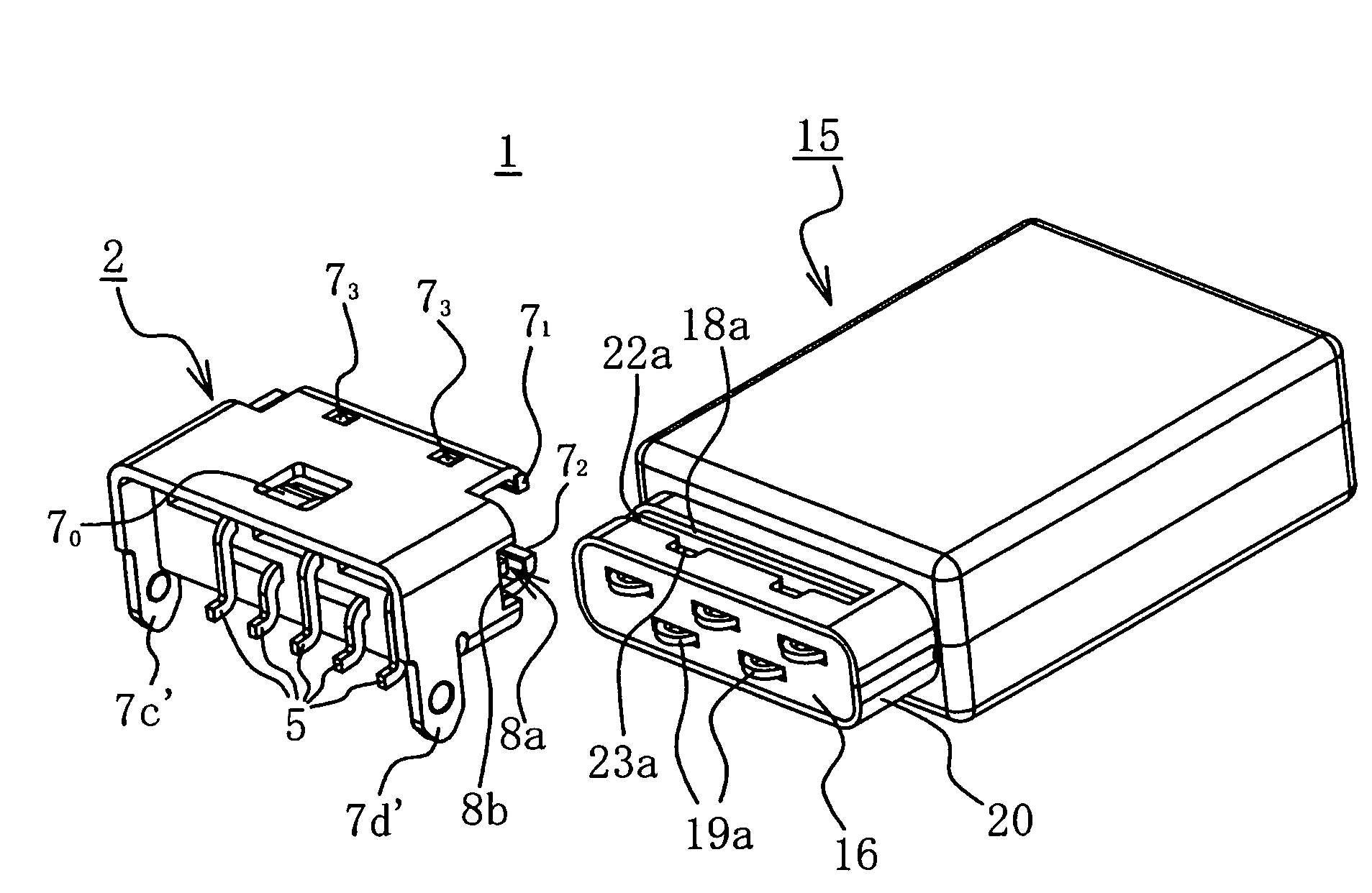
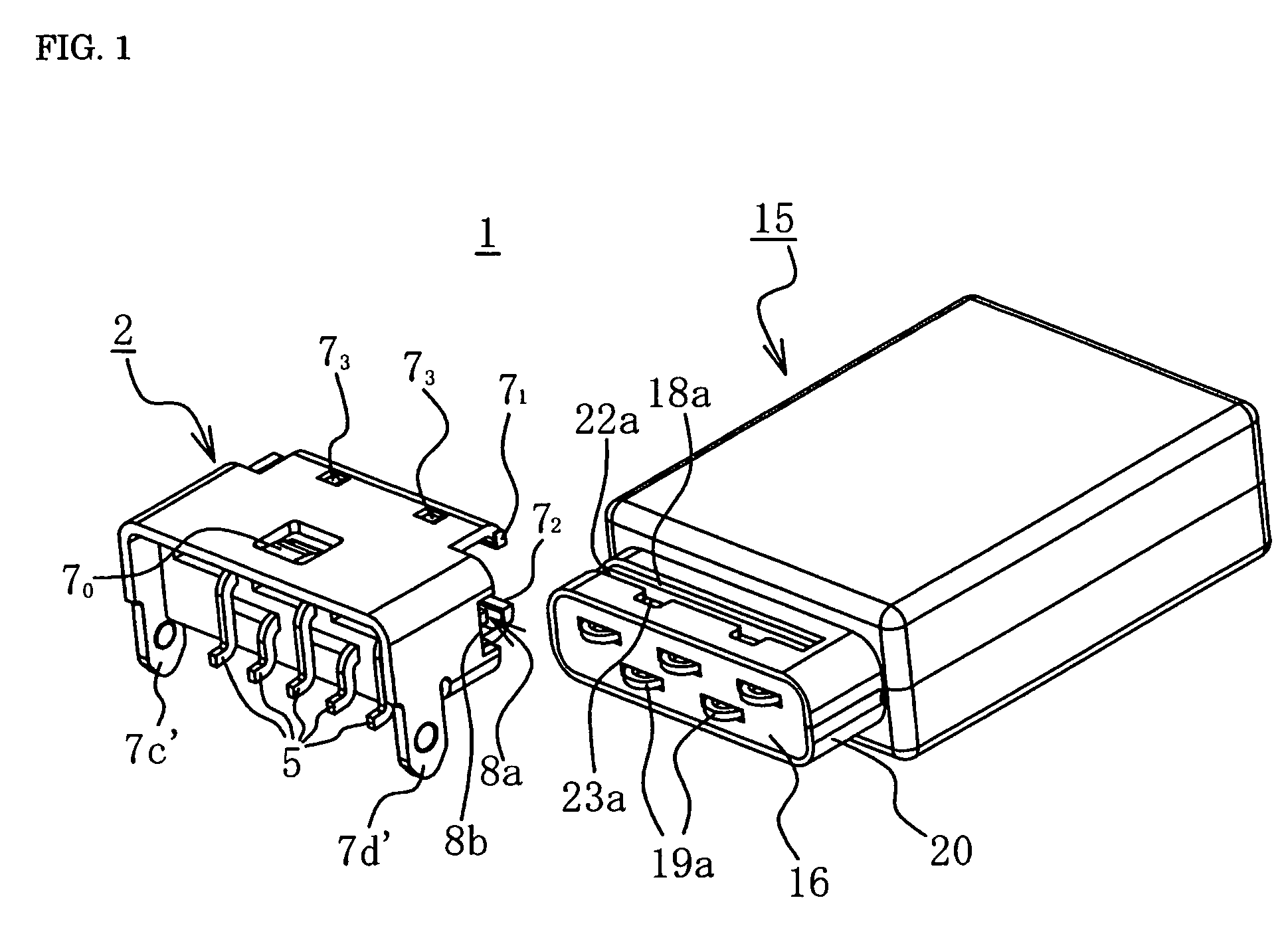
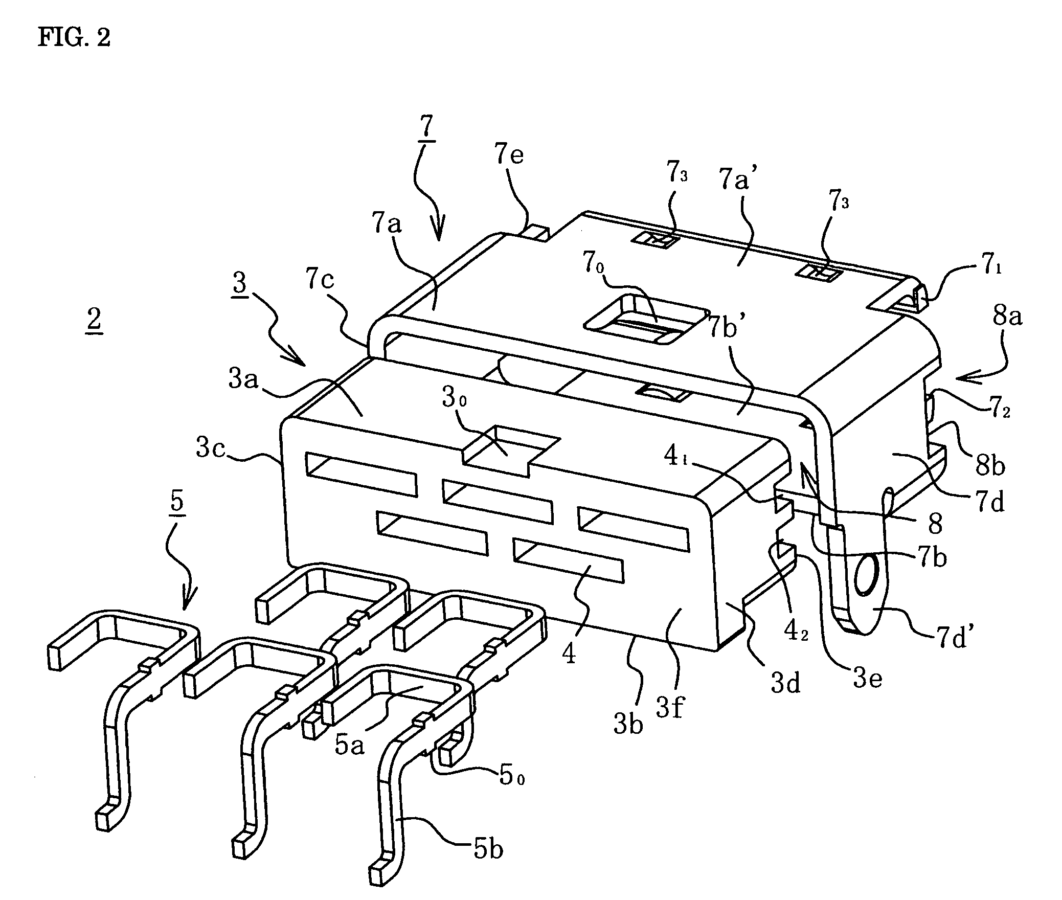
[0029]FIG. 1 is a perspective view of the female connector and male connector of the first embodiment of the present invention prior to being joined together, FIG. 2 is an exploded perspective view of the female connector, FIG. 3 is an exploded perspective view of the male connector, and FIG. 4 is a horizontal cross-sectional view of the female connector and male connector in the joined state.

[0030]As shown in FIG. 1, the pair of connectors 1 of this embodiment consists of a female connector 2 and a male connector 15 that is connected by being slid into the female connector 2 horizontally either from the left or right side.

[0031]The female connector 2 is attached to a printed circuit board or similar item. As shown in FIG. 2, it has a plurality of contact pins 5, a synthetic resin connector body 3 that has through-holes 4 into which the contact pins 5 are fitted, and a metal shell 7 that ensheathes the top and sides of the connector body 3.

[0032]The connector body 3 takes the form o...

embodiment 2

[0050]FIGS. 5 and 6 show the female connector and male connector of the second embodiment of the present invention, FIG. 5 is a perspective view of the female and male connectors prior to being joined together, while FIG. 6 is another perspective view of the female and male connectors in FIG. 5 from a different direction. Whereas the insertion opening of the connector 1 in Embodiment 1 described above is formed on either the left or the right side wall of the female connector, the insertion opening of the connector 1A of Embodiment 2 is provided on either the top or bottom wall thereof so as to permit connection by insertion in a vertical manner.

[0051]More specifically, as shown in FIGS. 5 and 6, the connector 1A is composed of a female connector 2A and a male connector 15A that is slid into the female connector 2A vertically either from above (as shown in the example) or from below so as to effect connection by insertion. The female connector 2A has a metal shell 7A and a connector...


PUM


Abstract

An apparatus is disclosed including a female and a male connector wherein the female connector has a resin first connector body to which a first set of contact pins are attached and a tubular metallic shell that ensheathes the outer surfaces of the first connector body. In front of the first tubular body, two pairs of opposing overhangs are formed projecting a certain distance from the forward surface of the first connector body, whereby one pair of overhangs is bent mid-way in a direction such that their forward edges approach each other but a certain gap is provided between them forming first and second guide latching portions. One of the other pair of opposing overhangs has an insertion opening formed in it, into which the male connector is inserted and passes through the aforementioned gap in order to affect connection while being guided by the first and second guide latching portions.

Description

BACKGROUND OF THE INVENTION[0001]The present invention relates to a female connector and a male connector and more particularly to a female connector and a male connector that can be connected by insertion either horizontally or vertically.[0002]Connectors are used for electrically connecting various component elements. Normally they come in pairs which are connected by insertion end-to-end from opposite directions. The conventional type of pair of connectors is such that the second connector is laterally inserted into the first connector.[0003]FIG. 7 is a perspective view of the connector disclosed in Japanese Utility Model JP-UM-A-5-6722, which is composed of a first connector 31 and a second connector 33, structured in such manner that a square U-shaped latching part 32 is provided around the periphery of the front end surface of the first connector 31 and a brim part 34 around the periphery of the front end surface of the second connector 33, whereby the brim part 34 of the seco...

Claims


Application Information

Patent Timeline
Patent Type & Authority Patents(United States)
IPC IPC(8): H01R13/64
CPCH01R23/6873H01R12/725H01R13/2428H01R13/658H01R13/639
Inventor TODA, KENICHISHIN, HONG FAN
Owner JST MFG CO LTD
Why Eureka
Try Eureka